
An assembly for generating electricity

a technology for generating electricity and assembly, which is applied in the direction of electric generator control, final product manufacturing, machines/engines, etc., can solve the problems of low maintenance and simple assembly design, and achieve the effect of maximising the output of the rotor uni

Active Publication Date: 2016-06-23
KOURIS PAUL STEVEN
View PDF7 Cites 8 Cited by
  • Summary
  • Abstract
  • Description
  • Claims
  • Application Information

AI Technical Summary

Benefits of technology

The present invention is a simple and easy to manufacture, transport, and install assembly for generating power in a water flow. It can be used in various waterways and can adapt to different water flow rates. The assembly is designed to be a free-standing unit and requires low maintenance. It is efficient and reliable. Additionally, it can be positioned along a waterway without affecting the flow of water. The assembly can operate effectively across the spectrum of flow rates of water in the body of water. It includes an inlet funnel to maximize water flow and minimize disruption to the vortex in the chamber. It also has a relatively large outlet area compared to the inlet area, which is important when the assembly is used in waterways with high flow rates. The assembly includes a gear box to tune the output of the rotor unit to the requirements of the electrical generator.

Problems solved by technology

The assembly is an uncomplicated design that is robust and reliable and requires low maintenance.

Method used


Image

  • An assembly for generating electricity
  • An assembly for generating electricity
  • An assembly for generating electricity

Examples


Embodiment Construction

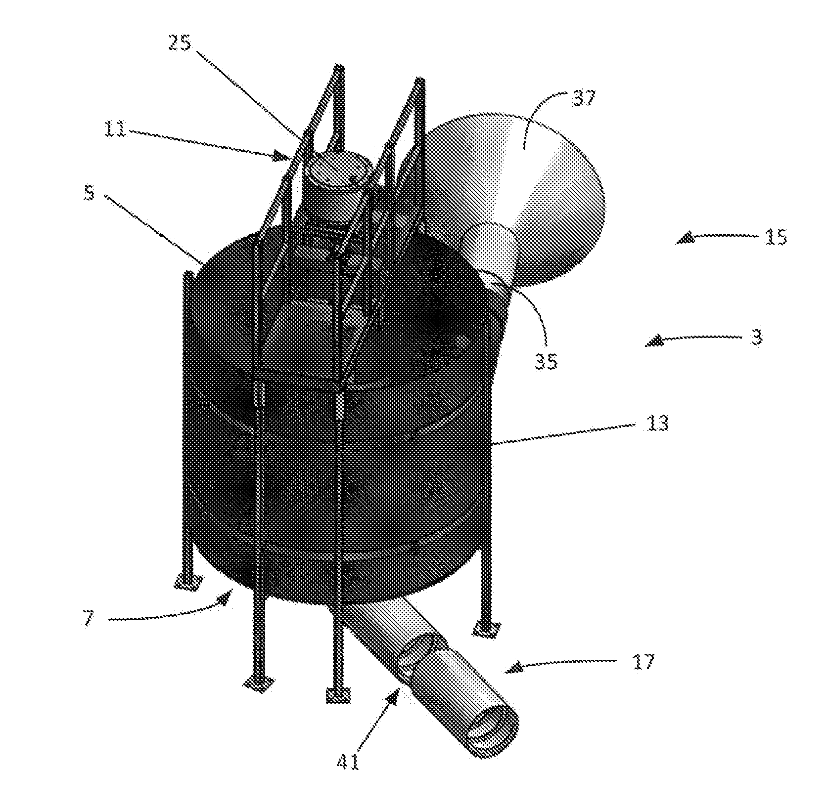
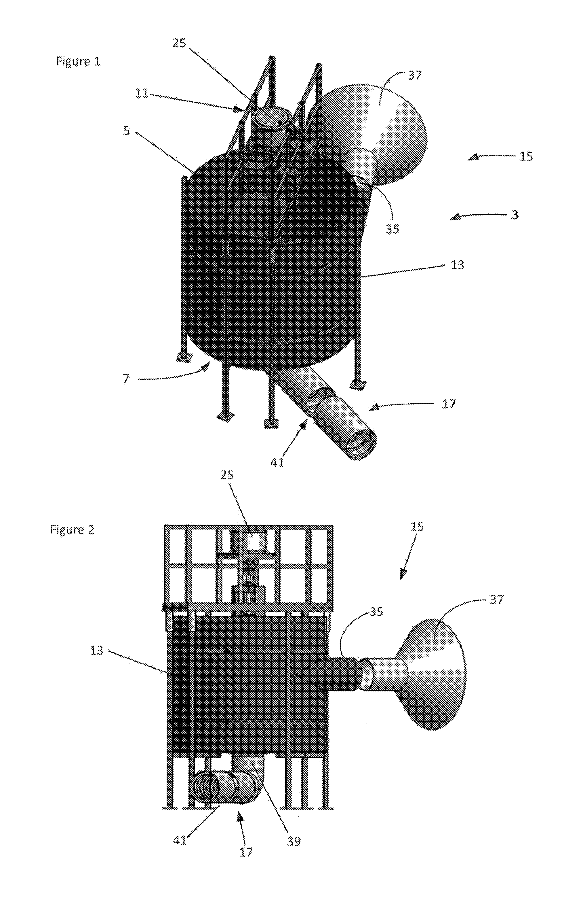
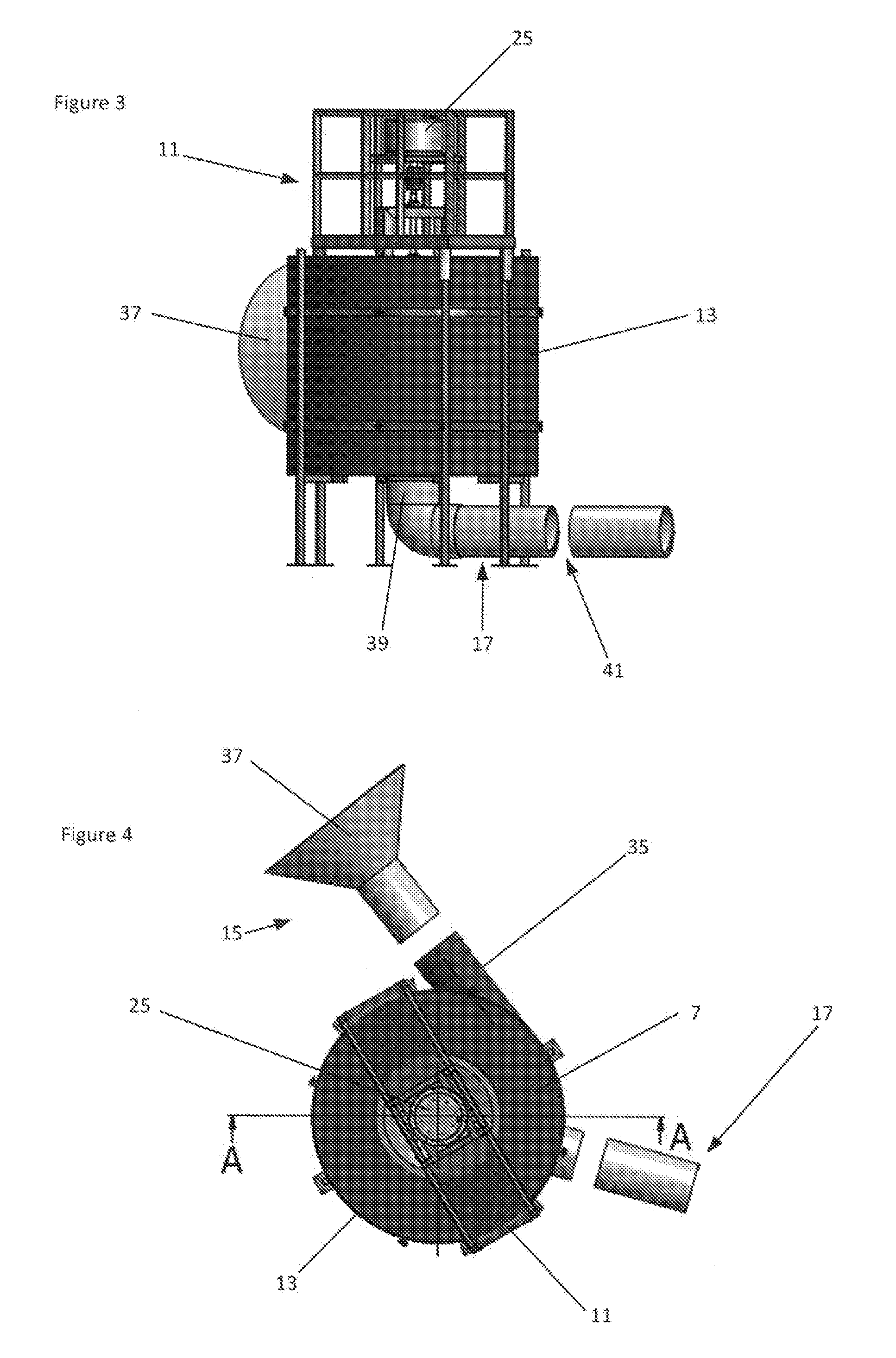
[0094]The embodiment of the electricity generation assembly 3 shown in the Figures is one of a number of possible embodiments of the invention. This particular embodiment is adapted to be positioned in a body of water or beside a body of water as a free-standing unit. The following description of the embodiment focuses on positioning the assembly in a body of water. Other embodiments of the invention are also adapted to be positioned in a body of water as a free-standing unit and further embodiments of the invention are adapted to be positioned beside a body of water.

[0095]With reference to the Figures, the assembly 3 includes a chamber 5 having a base 7, a cylindrical side wall 13 (having a cylindrical internal surface) extending upwardly from the base 7, an inlet 15 in the side wall 13, an outlet 17 in the base 7, a rotor unit having a shaft 19 and a rotor 21 mounted to the shaft 19 and located in and rotatable within the chamber 5 in response to water flow through the chamber 5, ...


PUM


Abstract

An assembly for generating electricity from flowing water includes a chamber having a base, a side wall extending from the base, a water inlet, and a water outlet, a rotor unit having a shaft and a rotor mounted to the shaft located in and rotatable in the chamber in response to water flow through the chamber, and an electrical generator coupled to the rotor unit for generating electricity in response to rotation of the rotor. The dimensions of the inlet, the outlet and the chamber and the positions of the inlet, the outlet and the rotor are selected to promote the formation of a vortex within the chamber when in use the assembly is located in a body of water or beside a body of water, in a waterway or beside a waterway, within an enclosed water conduit or beside an enclosed water conduit, and there is a flow of water through the chamber from the inlet to the outlet.

Description

FIELD OF THE INVENTION[0001]The present invention relates to an assembly for generating electricity.DESCRIPTION OF THE PRIOR ART[0002]International publication WO00 / 23708 in the name of the applicant discloses an invention of a water-driven assembly for generating electricity. The assembly takes advantage of energy of water flowing in a vortex, with the energy being the result of a combination of factors including the Coriolis force from the rotation of the Earth. This energy, which can be described as rotational kinetic energy, is different to energy generated by the fall of water.[0003]The applicant has carried out substantial research and development work in relation to the invention and part of this work has focused on developing an assembly that can be manufactured and transported and installed effectively and efficiently in or beside a wide range of bodies of water and can operate for long periods of time with minimal maintenance.SUMMARY OF INVENTION[0004]The present invention...

Claims


Application Information

Patent Timeline
IPC IPC(8): F03B13/10H02K7/18
CPCH02K7/1823F03B13/10F03B3/02F03B11/02F05B2240/132Y02E60/16Y02P70/50F03B3/04F03B13/08Y02E10/20
Inventor KOURIS, PAUL STEVEN
Owner KOURIS PAUL STEVEN
Learn More