Key sheet, light blocking effect sheet, push button switch and key sheet manufacturing method

a technology of push button switch and key sheet, which is applied in the direction of selector switch, electric apparatus, legends, etc., can solve the problems of deterioration of operational feel and increase of components

Inactive Publication Date: 2010-06-17
SEKISUI POLYMATECH CO LTD
View PDF19 Cites 39 Cited by
  • Summary
  • Abstract
  • Description
  • Claims
  • Application Information

AI Technical Summary

Benefits of technology

The technical effect of this patent is that it provides a way to stop light from leaking out around the edges of keys on a button switch without reducing its brightness.

Problems solved by technology

The technical problem addressed in this patent is to improve the operational feel and illumination luminance of an illumination type pushbutton switch without increasing the thickness of the pushbutton switch or the number of components and without reducing the illumination luminance caused by a dark print layer.

Method used


Image

  • Key sheet, light blocking effect sheet, push button switch and key sheet manufacturing method
  • Key sheet, light blocking effect sheet, push button switch and key sheet manufacturing method
  • Key sheet, light blocking effect sheet, push button switch and key sheet manufacturing method

Examples


examples

[0182]In the following, specific examples are described along with the brightness with which illumination is to be effected.

[0183]1. Preparation of Specimens: Using a polycarbonate resin film of a thickness of 300 μm as the base sheet (3), the following Specimens 1 through 5 were prepared.

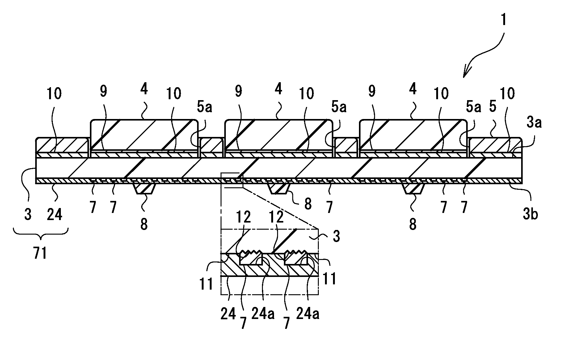
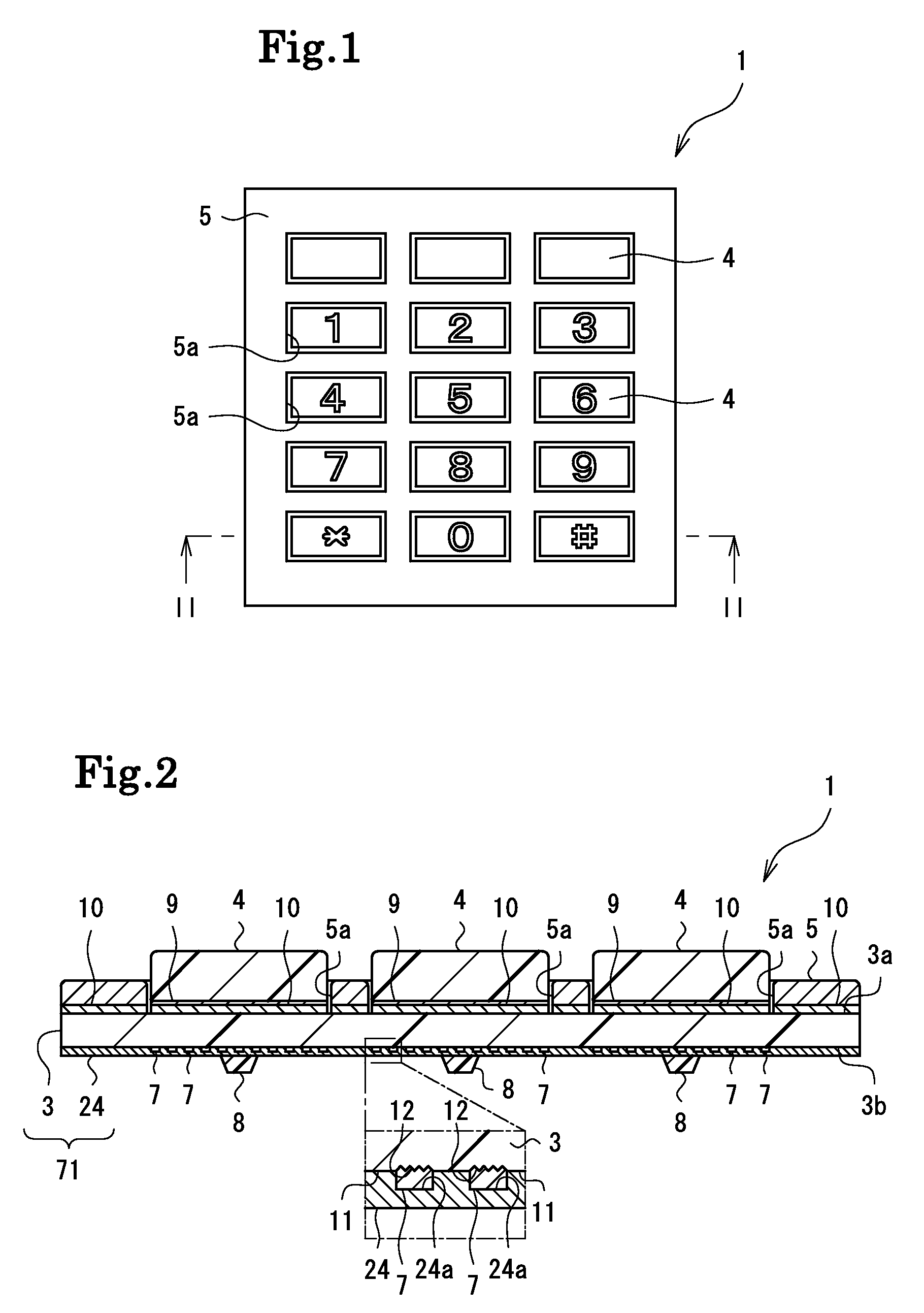
[0184]Specimen 1: the key tops (4) having the print layers (9) on the back surfaces thereof and the top cover (5) were fixed to the front surface (3a) of the base sheet (3) formed of a polycarbonate resin film of a thickness of 300 μm by means of the adhesion layers (10). Further, on the back surface (3b) of the base sheet (3), there were formed the diffusion portions (7) arranged in a dot-like dispersed fashion in correspondence with the configuration of the key tops (4) by printing using a solvent type printing ink, and then the dark print layer (24) formed of an aqueous acrylic resin was formed by printing on the entire back surface (3b) of the base sheet (3) covering the diffusion portions (7)....


PUM

PropertyMeasurementUnit
Transparencyaaaaaaaaaa

Abstract

Provided is a key sheet or a lightproof light guiding sheet guiding light efficiently through an interior of the key sheet and preventing light leakage through a periphery of key tops. On a base sheet, a transparent resin layer, and further, a lightproof dark print layer are provided as needed, with at least one of the transparent resin layer and the lightproof dark print layer being formed of a non-corrosive coating liquid. Further, a smooth surface is formed between the base sheet and the dark print layer.

Description


Claims


Application Information

Patent Timeline
Owner SEKISUI POLYMATECH CO LTD
Why Eureka
Try Eureka