Structure of light bulb

a technology of light bulb and structure, which is applied in the direction of multiple discharge path lamps, semiconductor devices of light sources, lighting and heating apparatus, etc., can solve the problems of high power consumption, wasting energy, burning or damage to surrounding objects, etc., to enhance the practicability of the present invention, and increase the angular range of illumination

Inactive Publication Date: 2010-06-17
U HOW
View PDF6 Cites 77 Cited by
  • Summary
  • Abstract
  • Description
  • Claims
  • Application Information

AI Technical Summary

Benefits of technology

[0006]A primary objective of the present invention is to provide a light bulb comprising light guide arranged inside a bulb body for guiding light from an internal light source provided by a light-emitting diode (LED) to increase the angular range of illumination thereby enhancing the practicability of the present invention.
[0007]Another objective of the present invention is to provide a light bulb comprising a light guide that is subjected to treatments to increase the angular range of illumination thereby enhancing the versatility of the present invention.
[0008]A further objective of the present invention is to provide a light bulb comprising an internal light source inside a bulb body provided by an LED, which features operation safety and extended lifespan thereby enhancing the practicability of the present invention.
[0009]Yet a further objective of the present invention is to provide a light bulb, which comprises components that can be assembled in a simple process to form a simple structure so that the light bulb can be easily manufactured with reduced costs, thereby enhancing the practicability of the present invention.
[0010]To realize the above objectives, the present invention provides a light bulb comprising a bulb body, a light guide, and at least one light-emitting diode (LED). The bulb body comprises a light-transmitting shell and a conductive base. The light-transmitting shell is mounted to the base. A circuit board is fixed at one side of the base and is in electrical connection with the base. The LED is mounted to the circuit board that is arranged at one side of the base, and the LED is in electrical connection with the circuit board to provide an internal light source. The light guide is arranged inside the bulb body and has an end forming a cavity that receives the LED therein, whereby the light guide is set erect on the base. As such, advantages of easy manufacturing, reduced costs, operation safety, increased angular range of illumination, and extended lifespan can be provided.

Problems solved by technology

However, the conventional lighting devices suffer certain disadvantages, including high power consumption, which leads to wasting of energy, high heat generation, which may cause burning or damage to surrounding articles and objects, short lifespan, which requires frequent replacement and maintenance, and monotonous outer contours, which lacks sense of art.
Further due to the drawback of high heat generation of the conventional incandescent bulbs that causes burning and damage of surrounding articles and objects, the power-saving bulbs are rapidly replacing the incandescent bulbs and become the main stream in the market of lighting instruments.
However, the lighting offered by the LEDs is subjected to constraint of directionality.
All these LEDs, even the diffusive type, are subjected to a certain extent of limitation in the illumination of light thereof.
Thus, to apply LEDs to lighting of various applications without being subjected to such a constraint in the angular range of illumination is now one of the major challenges of the industry.

Method used


Image

  • Structure of light bulb
  • Structure of light bulb
  • Structure of light bulb

Examples


Embodiment Construction

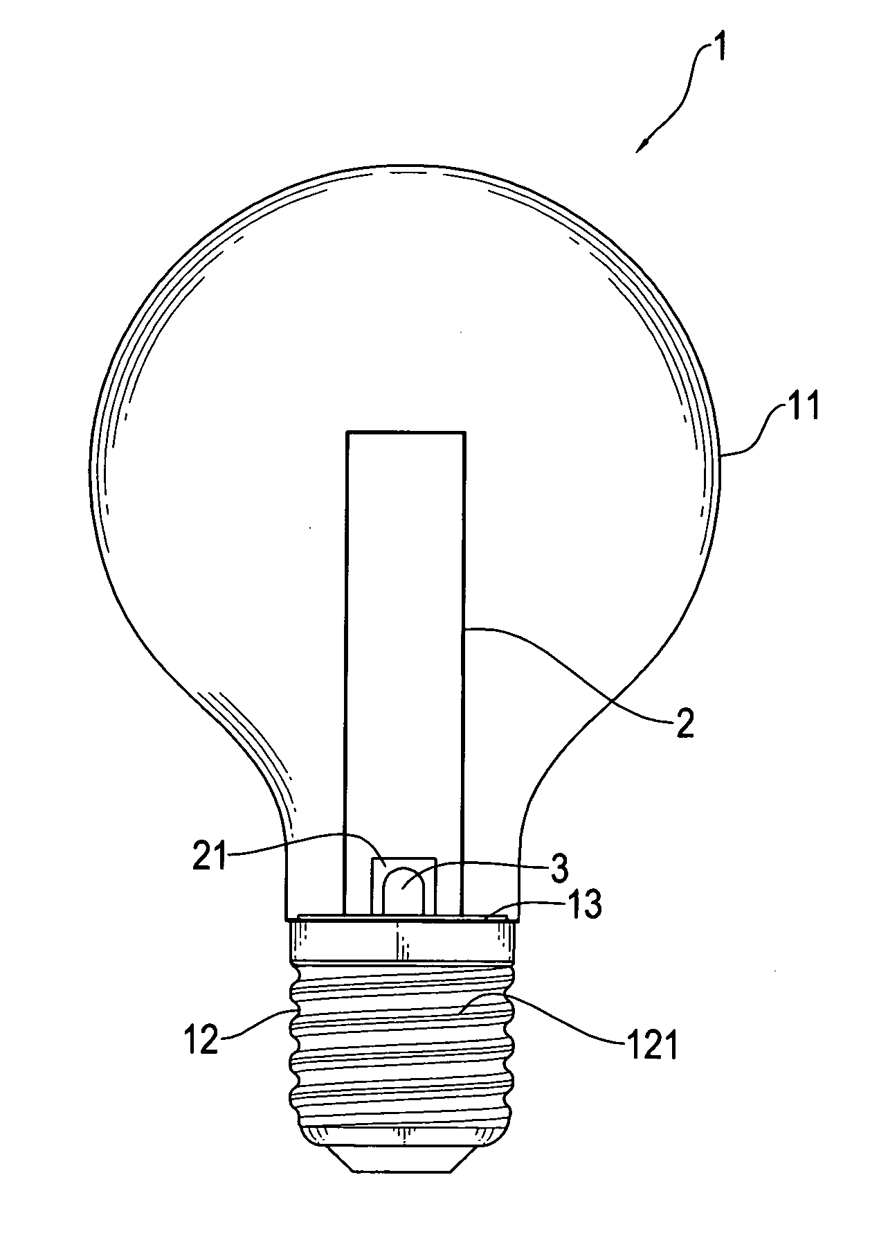
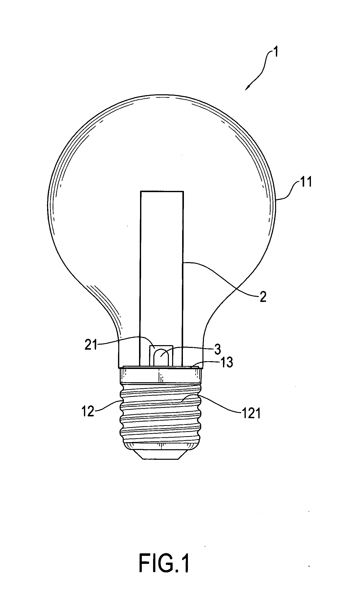
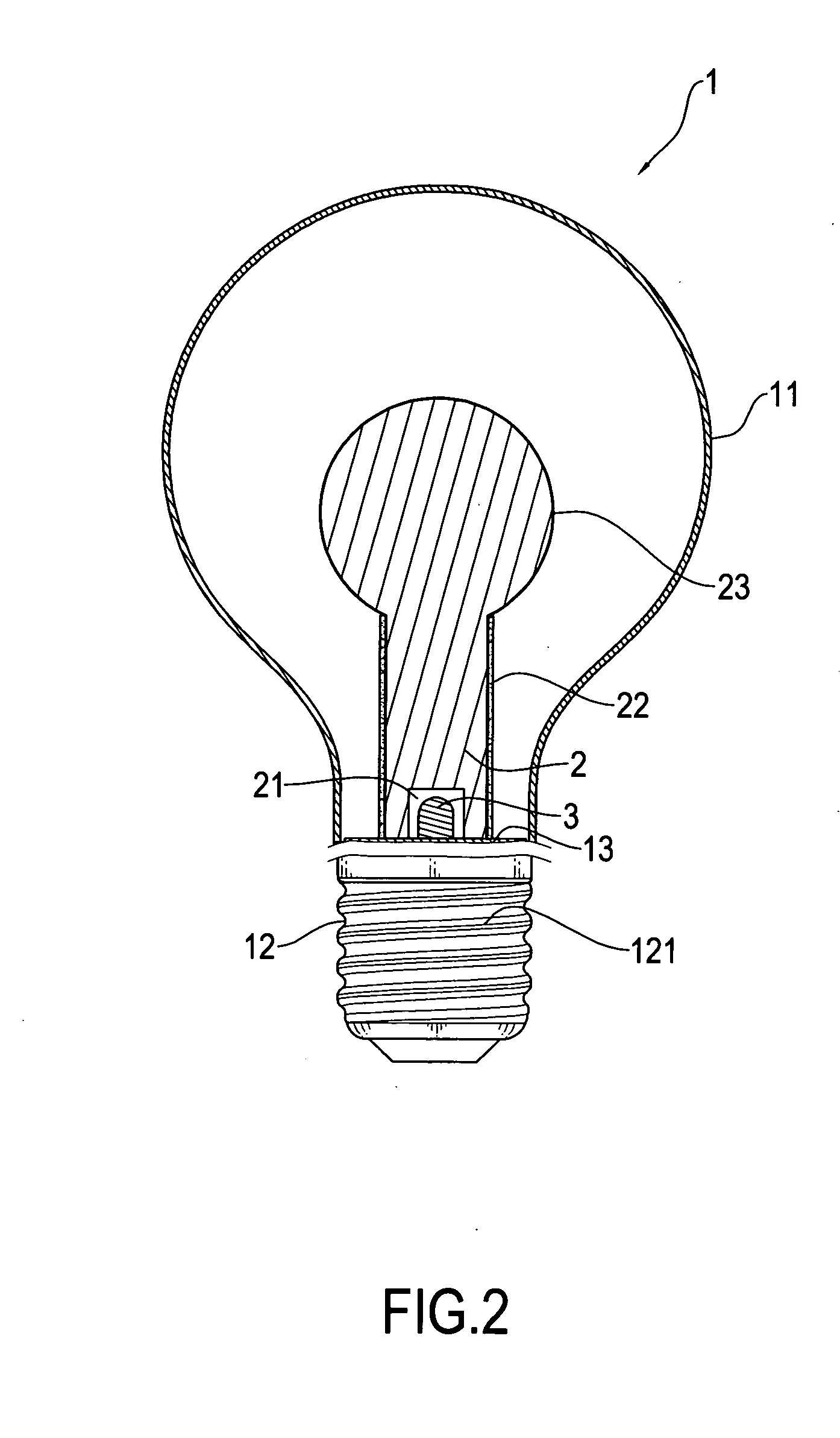
[0018]With reference to FIGS. 1 and 6, which respectively illustrates a side elevational view of a light bulb constructed in accordance with a first embodiment of the present invention and an application of the light bulb of the present invention, the light bulb of the present invention comprises a bulb body 1, a light guide 2, and at least one light-emitting diode (LED) 3.

[0019]The bulb body 1 comprises a light-transmitting material 11, preferably made in the form of a bulb shell, which in the embodiment illustrated comprises clear glass, but can alternatively be clear plastics, frosted glass, or frosted plastics, and an electrically conductive base 12, which in the embodiment illustrated has a helical and electrically conductive configuration 121, comprised of a ring contact and a tip contact, for threading engagement with a socket 4 of an external power source to establish electrical connection therebetween. The light-transmitting material or shell 11 is mounted to the base 12 in...


PUM


Abstract

A light bulb includes a bulb body, a light guide, and at least one light-emitting diode (LED). The bulb body includes a light-transmitting shell and a conductive base. The light-transmitting shell is mounted to the base. A circuit board is fixed at one side of the base and is in electrical connection with the base. The LED is mounted to the circuit board that is arranged at one side of the base, and the LED is in electrical connection with the circuit board to provide an internal light source. The light guide is arranged inside the bulb body and has an end forming a cavity that receives the LED therein, whereby the light guide is set erect on the base. As such, advantages of easy manufacturing, reduced costs, operation safety, increased angular range of illumination, and extended lifespan can be provided.

Description

FIELD OF THE INVENTION[0001]The present invention relates to a structure of a light bulb, and in particular to a light bulb comprising a bulb body inside which a light guide is arranged to guide light from a light-emitting diode for increasing the angular range of illumination and to extend the lifespan thereof for being applicable to lighting in various sites and locations.BACKGROUND OF THE INVENTION[0002]The conventional incandescent lamps have been widely used. However, the conventional lighting devices suffer certain disadvantages, including high power consumption, which leads to wasting of energy, high heat generation, which may cause burning or damage to surrounding articles and objects, short lifespan, which requires frequent replacement and maintenance, and monotonous outer contours, which lacks sense of art.[0003]Recently, with the costs of raw material increasingly raised and shortage of energy, to reduce waste of energy, the lighting industry are developing power-saving l...

Claims


Application Information

Patent Timeline
Patent Type & Authority Applications(United States)
IPC IPC(8): H01J61/94
CPCF21K9/135F21K9/52F21Y2101/02F21V7/043F21V13/02F21V3/02F21K9/232F21K9/61F21Y2115/10
Inventor WU, PING-JUWU, PING-CHEN
Owner U HOW
Why Eureka
Try Eureka