Steering control apparatus

a control apparatus and steering technology, applied in the direction of steering initiation, instruments, vessel construction, etc., can solve the problems of transmission loss of steering assist force, other rack-and-pinion mechanism does not move into a proper engagement position,

Inactive Publication Date: 2010-06-17
HITACHI AUTOMOTIVE SYST LTD
View PDF6 Cites 67 Cited by
  • Summary
  • Abstract
  • Description
  • Claims
  • Application Information

AI Technical Summary

Benefits of technology

[0004]It is accordingly an object of the present invention to provide a steering control apparatus in which two steer

Problems solved by technology

The above modified dual pinion type power steering apparatus however has a problem that, when one of the rack-and-pinion mechanisms moves into a proper engagement position, there exerts a rotational torsional force from the pinion shaft on the rack shaft

Method used


Image

  • Steering control apparatus
  • Steering control apparatus
  • Steering control apparatus

Examples


first embodiment

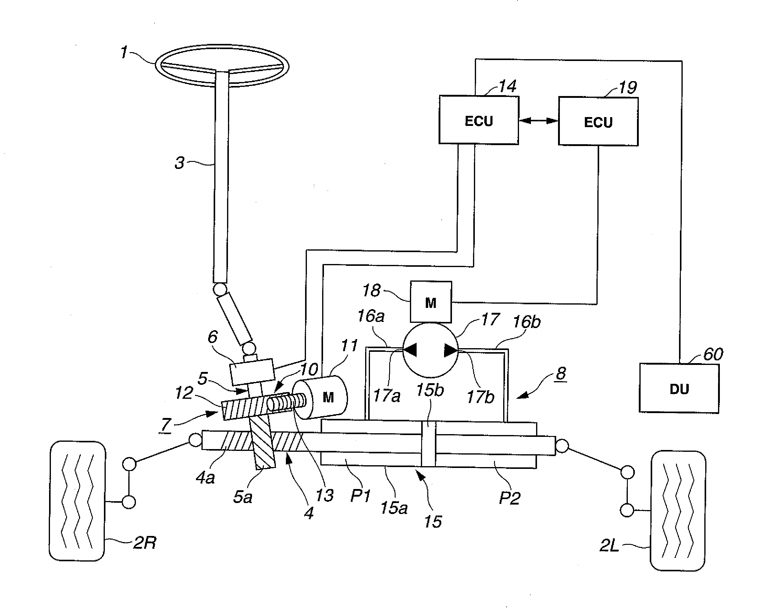
[0018]Referring to FIG. 1, a steering control apparatus for an automotive vehicle according to the first embodiment of the present invention is designed as a rack-and-pinion type power steering apparatus that establishes a mechanical link between a steering wheel 1 and steerable road wheels 2L and 2R of the vehicle.

[0019]More specifically, the steering control apparatus of the first embodiment includes a steering shaft 3 connected to the steering wheel 1, a rack shaft 4 connected to the vehicle road wheels 2L and 2R and having rack teeth 4a in a given axial range and a pinion shaft 5 having pinion teeth 5a at one end thereof engaged with the rack teeth 4a and connected at the other end to the steering shaft 3 via a torsion bar so as to be rotatable relative to the steering shaft 3. With the application of a steering force to the steering wheel 1 by a vehicle driver, the steering force is transmitted from the steering wheel 1 to the steering shaft 3 so that the steering shaft 3 rotat...

second embodiment

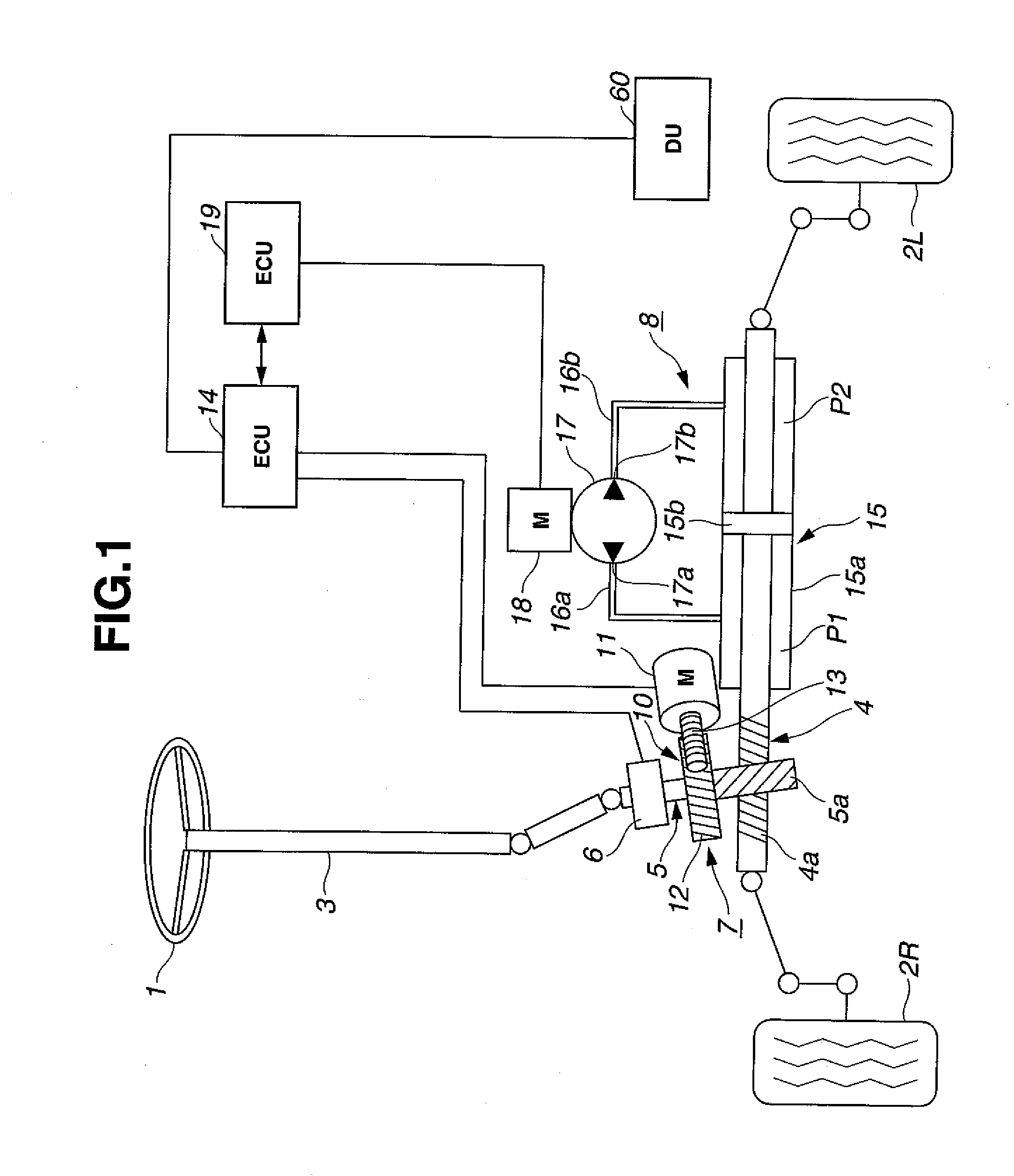
[0034]A steering control apparatus of the second embodiment is structurally similar to that of the first embodiment, except that: the steering control apparatus utilizes a steering column assembly and adopts a column assist type power steering system as shown in FIG. 2

[0035]The steering column assembly is connected to the pinion shaft 5 so that the steering shaft 3a and the pinion shaft 5 can rotate together with each other. As shown in FIG. 2, this steering column assembly has a steering shaft 3a connected to the steering wheel 1 and a steering column 3b rotatable relative to the steering shaft 3a. The steering shaft 3a and the steering column 3b are coupled together via a torsion bar.

[0036]The torque sensor 6 is disposed on the steering column 3b so as to surround an outer periphery of the joint between the steering shaft 3a and the steering column 3b.

[0037]The first steering mechanism 7 is disposed around the steering column 7 rather than around the pinion shaft 5. More specific...

third embodiment

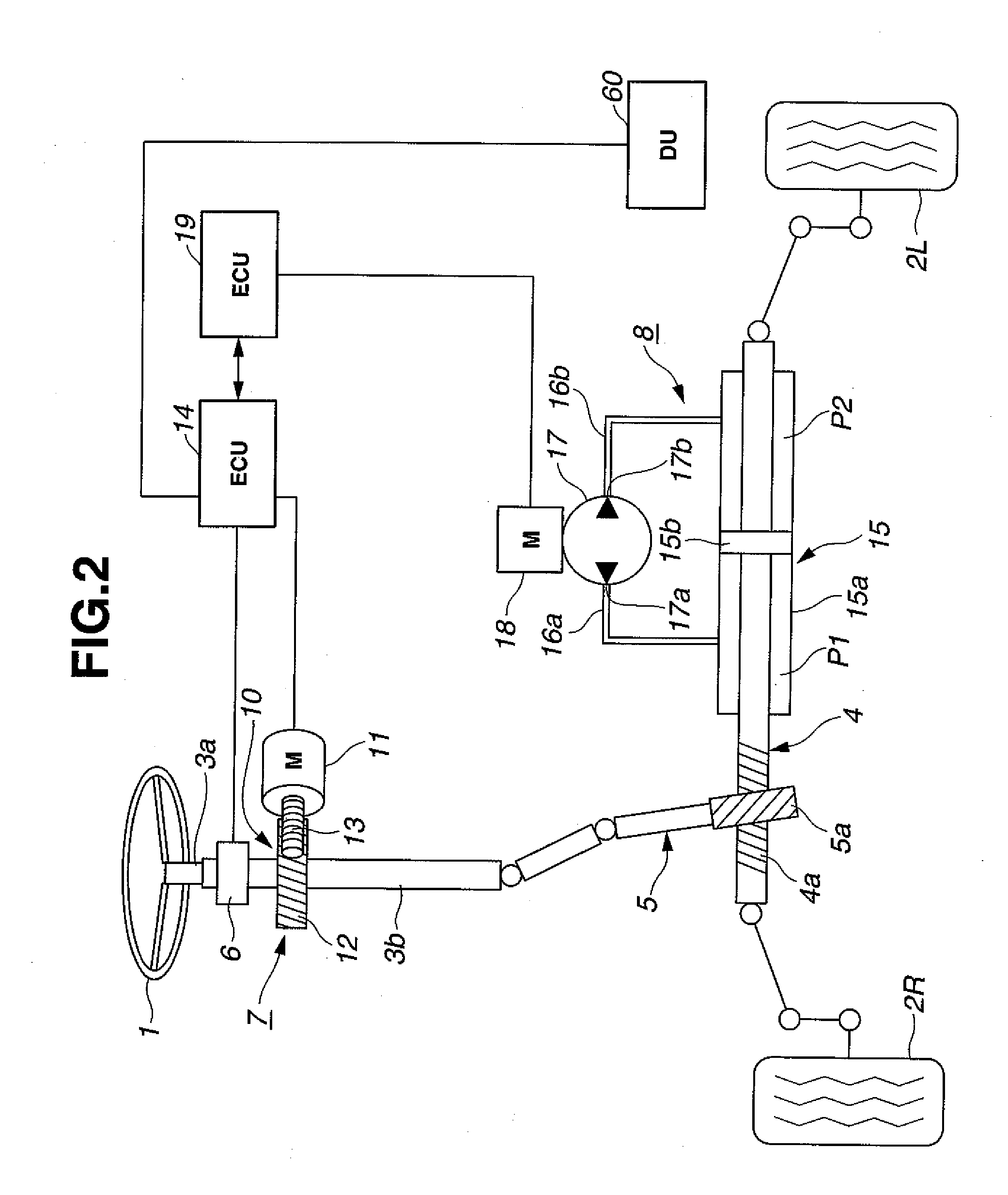
[0039]A steering control apparatus of the third embodiment is structurally similar to that of the first embodiment, except that the steering control apparatus adopts a rack assist type power steering system as shown in FIG. 3.

[0040]The rack shaft 4 has a ball screw portion 4b formed in a different axial range from the rack teeth 4a.

[0041]The first and second steering mechanisms 7 and 8 are disposed on opposite sides of the rack shaft 4 in parallel with each other.

[0042]In the first steering mechanism 7, the reduction gear 10 has a ball nut 20 movably engaged on the ball screw portion 14b of the rack shaft 14 and a belt 21 looped around the ball nut 20 and the drive shaft 11a of the first steering force generation motor 11 so as to, when the first steering force generation motor 11 is driven under the control of the first steering force control unit 14, transmit the torque of the first steering force generation motor 11 to the ball nut 20 and thereby rotate the ball nut 20 around th...


PUM


Abstract

A steering control apparatus includes a rack shaft connected to steerable wheels and having rack teeth in a given axial range, a first steering mechanism having a reduction gear and a first electric motor to apply a drive force to the rack shaft through the reduction gear, a second steering mechanism having a second electric motor, a power cylinder equipped with hydraulic pressure chambers, an oil pump driven by the second electric motor to provide a supply of hydraulic oil to the hydraulic pressure chambers such that the power cylinder applies a driving force to the rack shaft in accordance with a pressure difference between the hydraulic pressure chambers and a switching unit capable of selectively switching the supply of hydraulic oil from the oil pump to the hydraulic pressure chambers, and a control device that controls the first and second electric motors in response to a driver's steering operation.

Description

BACKGROUND OF THE INVENTION[0001]The present invention relates to a steering control apparatus for an automotive vehicle and, more particularly, to a steering control apparatus having two independently operable steering mechanisms.[0002]Japanese Laid-Open Patent Publication No. 2002-154442 discloses one type of steering control apparatus, called a dual pinion type electric power steering apparatus that has two rack-and-pinion steering mechanisms. More specifically, the dual pinion type electric power steering apparatus includes a rack shaft having first and second rack teeth formed at axially different positions, a first pinion shaft coupled to a steering wheel and having pinion teeth engaged with the first rack teeth, a second pinion shaft having pinion teeth engaged with the second rack teeth, an electric motor coupled to the second pinion shaft via a reduction gear, a torque sensor mounted on the first pinion shaft and connected with the electric motor and a control unit arranged...

Claims


Application Information

Patent Timeline
IPC IPC(8): G06F19/00B62D5/30B62D5/04B62D5/06B62D5/07B62D5/083B62D5/087B62D5/10B62D5/22
CPCB62D5/0463B62D5/09B62D5/065
Inventor SHIINO, KOHTAROYODA, TOSHIRO
Owner HITACHI AUTOMOTIVE SYST LTD
Why Eureka
Try Eureka