
Solar receiver

a solar receiver and receiver technology, applied in the field of solar receivers, can solve the problems of increased cost, inefficiency, malfunction, etc., and achieve the effect of reducing the cost of solar receivers, increasing the cost, and improving the efficiency of solar receivers

Inactive Publication Date: 2010-06-24
SKYLINE SOLAR INC
View PDF16 Cites 53 Cited by
  • Summary
  • Abstract
  • Description
  • Claims
  • Application Information

AI Technical Summary

Problems solved by technology

The waste heat generated in the solar receivers used in CPV systems may raise the cell temperature subjecting the solar cells to thermal stresses causing malfunction, inefficiencies, and increased costs.
However, current solar receivers are not sufficiently efficient from a thermal energy transfer standpoint while at the same time sufficiently simple, rugged, compact, and lightweight to be transportable, susceptible to on-site assembly, or efficiently stored.

Method used


Image

  • Solar receiver
  • Solar receiver
  • Solar receiver

Examples


example

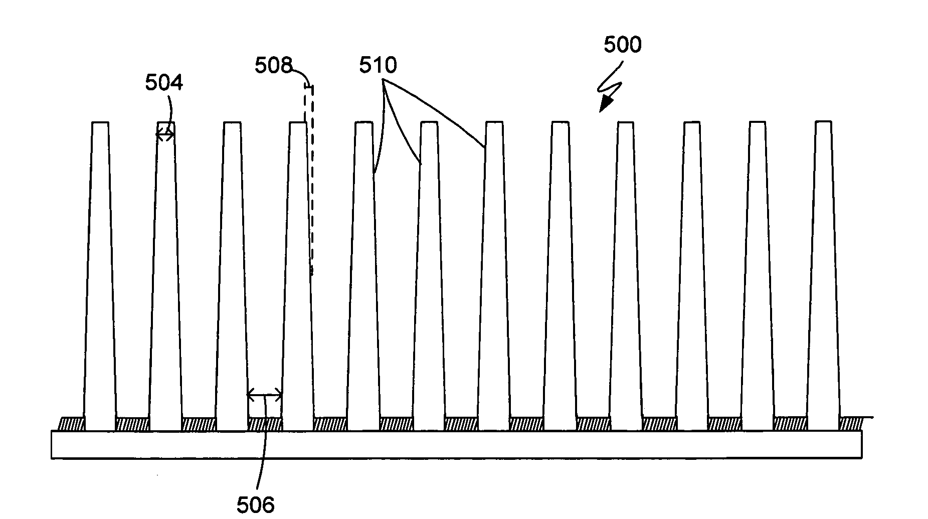
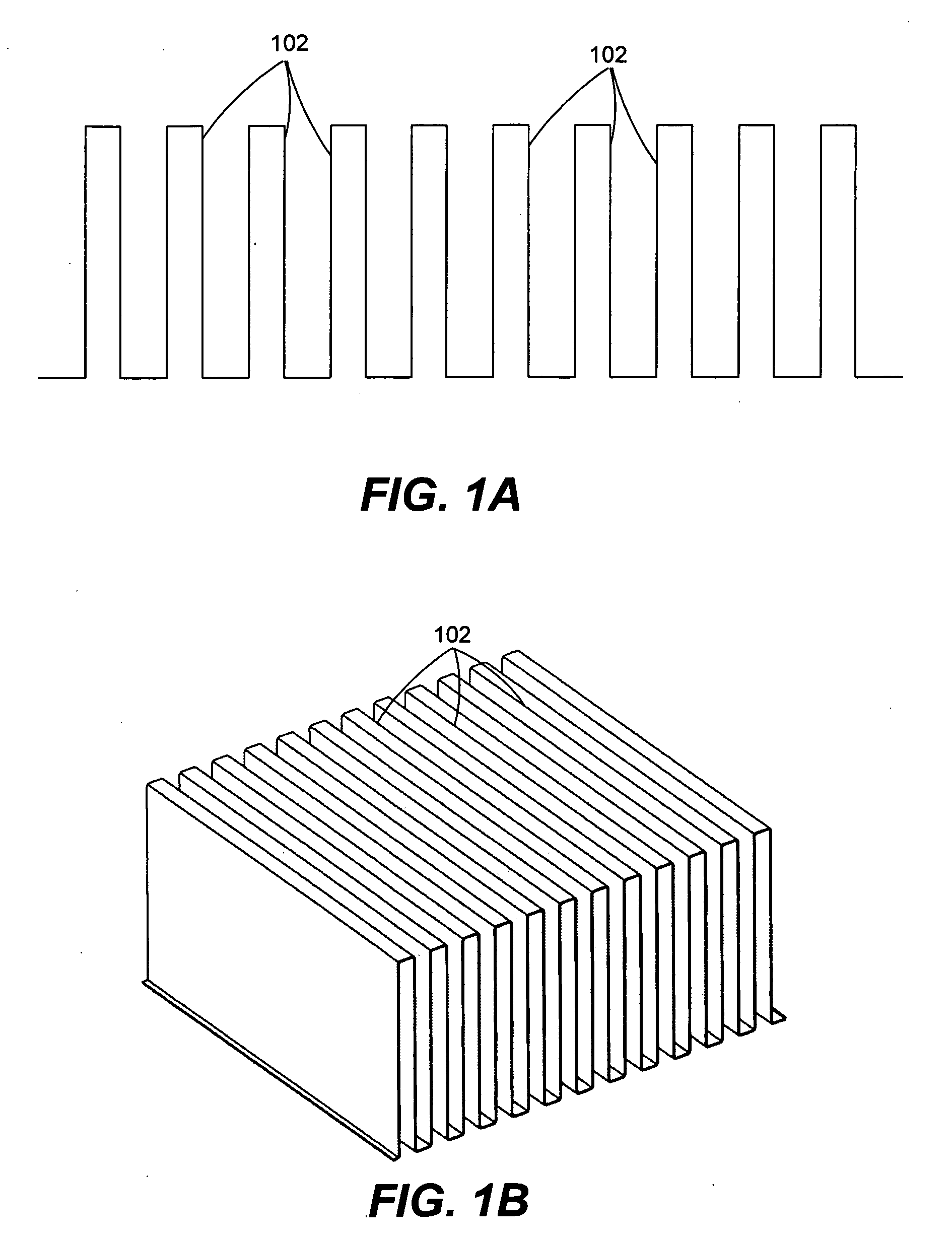
[0041]Examples are described herein for exemplary purposes only and not intended to be limiting. An example heat sink fin may be made from a continuous sheet of material, such as aluminum. The sheet of material may have a thickness of about 0.020 inches. Each fin may have a fin length of about 5.50 inches and a fin height of about 3 inches. Thus, the ratio of fin height to fin length may be 3 inches / 5.5 inches=0.55.

[0042]Each fin may have a fin pitch of about 0.25 inches and about 5.5 undulations along the fin length axis. Each fin may have an undulation amplitude of about 0.050 inches, an undulation period of about 1 inch, and an undulation radius of about 1.262 inches. The heat sink may be formed to any desired length. In one embodiment, the heat sink may have a length of about 52 inches, which results in the formation of about 208 fins.

[0043]FIGS. 4A and 4B illustrates an embodiment of a stackable solar receiver. FIG. 4A illustrates a cross-sectional side view of a solar receiver...


PUM


Abstract

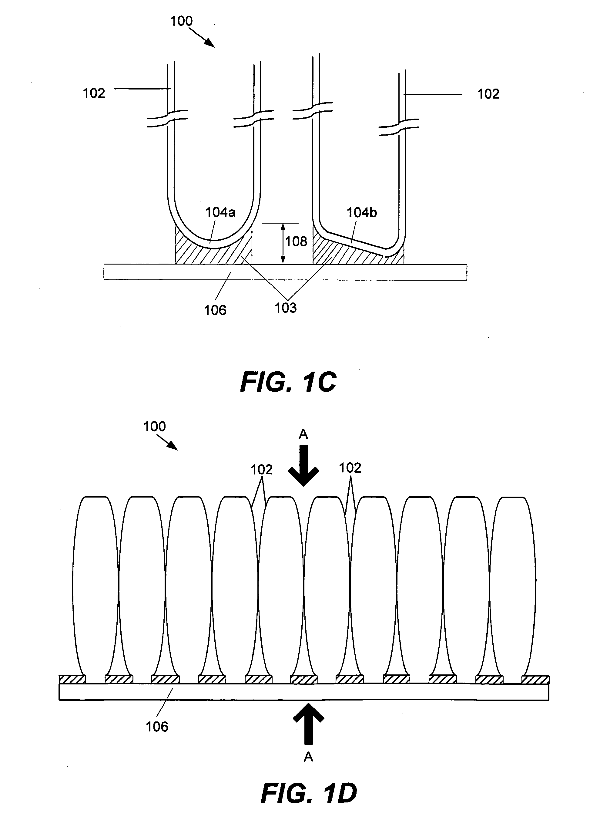
In one embodiment, a solar receiver has a base plate having a first surface and a second surface, a plurality of solar cells positioned over and supported by the first surface of the base plate, and a multiplicity of fins extending outwardly from the second surface of the base plate. Each of the multiplicity of fins has a fin height axis extending generally perpendicular relative to the base plate, a fin length axis extending generally in parallel with the base plate, and a bottom end attached to the second surface of the base plate, wherein each of the multiplicity of fins are formed from a single, continuous sheet of metal arranged in a serpentine configuration, and wherein each of the multiplicity of fins have a plurality of undulations along the length axis of the fin.

Description

FIELD OF THE INVENTION[0001]The present disclosure relates generally to solar receivers. More particularly, the present disclosure relates generally to solar receivers having a heat sink.BACKGROUND OF THE INVENTION[0002]The highest cost components of a solar photovoltaic (PV) system are the solar cells that convert sunlight to electricity by the photoelectric effect. To use these cells more effectively, concentrating photovoltaic (CPV) systems focus sunlight from a larger aperture onto a smaller cell area. The waste heat generated in the solar receivers used in CPV systems may raise the cell temperature subjecting the solar cells to thermal stresses causing malfunction, inefficiencies, and increased costs.[0003]Heat sinks may be used to absorb and dissipate the heat from the solar receivers. However, current solar receivers are not sufficiently efficient from a thermal energy transfer standpoint while at the same time sufficiently simple, rugged, compact, and lightweight to be trans...

Claims


Application Information

Patent Timeline
IPC IPC(8): F24J2/24F24S10/70
CPCF24J2/07H01L31/054Y02E10/52H01L31/052F24S20/20
Inventor WELLS, JASON R.DO, KHIEM B.
Owner SKYLINE SOLAR INC
Learn More