Wave Energy Capturing Device

a technology of wave energy and capturing device, which is applied in the direction of electric generator control, machines/engines, mechanical equipment, etc., can solve the problems of less efficient operation of devices in calmer ocean conditions, large and heavy devices, and inefficient operation, etc., and achieve the effect of reducing the wave force applied to the paddl

Inactive Publication Date: 2010-06-24
BIOPOWER SYSTEMS PTY LTD
View PDF37 Cites 21 Cited by
  • Summary
  • Abstract
  • Description
  • Claims
  • Application Information

AI Technical Summary

Benefits of technology

[0015]Preferably, a machine is connected to said energy transfer member for extracting energy from oscillatory motion of said paddle. The machine is preferably adapted to receive a torque from said energy transfer member. The machine can preferably function as both a motor and a generator. More preferably, said machine incorporates a permanent magnet synchronous motor / generator. In a preferred form, said motor / generator is completely sealed, and may be filled with inert gas under pressure, to prevent internal corrosion or leaking.
[0017]Preferably, the configuration in which the wave forces applied to said paddle are reduced is a configuration in which the mean position of the longitudinal axis of the paddle is further inclined relative to a vertical plane drawn perpendicular to the direction of wave propagation. Depending on the value indicated by the sensor, the paddle may be moved into and maintained in a configuration substantially parallel to the direction of wave propagation to minimise the wave forces applied to the paddle.
[0028]Preferably, a machine is connected to said paddle for extracting energy from oscillatory motion of said paddle. The machine is preferably adapted to receive a torque from said energy transfer member. The machine can preferably function as both a motor and a generator. More preferably, said machine incorporates a permanent magnet synchronous motor / generator. In a preferred form, said motor / generator is completely sealed, and may be filled with inert gas under pressure, to prevent internal corrosion or leaking.
[0030]Preferably, the configuration in which the wave forces applied to said paddle is reduced is a configuration in which the mean position of the longitudinal axis of the paddle is further inclined relative to a vertical plane drawn perpendicular to the direction of wave propagation. Depending on the value indicated by the sensor, the paddle may be moved into and maintained in a configuration substantially parallel to the direction of wave propagation to minimise the wave forces applied to the paddle.
[0040]Preferably, a machine is connected to said paddle for extracting energy from oscillatory motion of said paddle. The machine is preferably adapted to receive a torque from said energy transfer member. The machine can preferably function as both a motor and a generator. More preferably, said machine incorporates a permanent magnet synchronous motor / generator. In a preferred form, said motor / generator is completely sealed, and may be filled with inert gas under pressure, to prevent internal corrosion or leaking.
[0042]Preferably, the configuration in which the wave forces applied to said paddle is reduced is a configuration in which the mean position of the longitudinal axis of the paddle is further inclined relative to a vertical plane drawn perpendicular to the direction of wave to propagation. Depending on the value indicated by the sensor, the paddle may be moved into and maintained in a configuration substantially parallel to the direction of wave propagation to minimise the wave forces applied to the paddle.

Problems solved by technology

A disadvantage of making wave energy capturing devices strong enough to withstand extremely high wave forces is that the devices tend to be very large and heavy.
A disadvantage of designing the devices to avoid a large amount of the wave force, in order to handle extreme ocean conditions, is that the devices operate less efficiently in calmer ocean conditions.
A further disadvantage of known wave energy capturing devices is that they operate inefficiently when the direction of wave propagation moves out of alignment with the fixed alignment of the paddle.
Another disadvantage of known wave energy capturing devices is that the solid paddle tends to reflect, rather than capture, wave energy.

Method used


Image

  • Wave Energy Capturing Device
  • Wave Energy Capturing Device
  • Wave Energy Capturing Device

Examples


Embodiment Construction

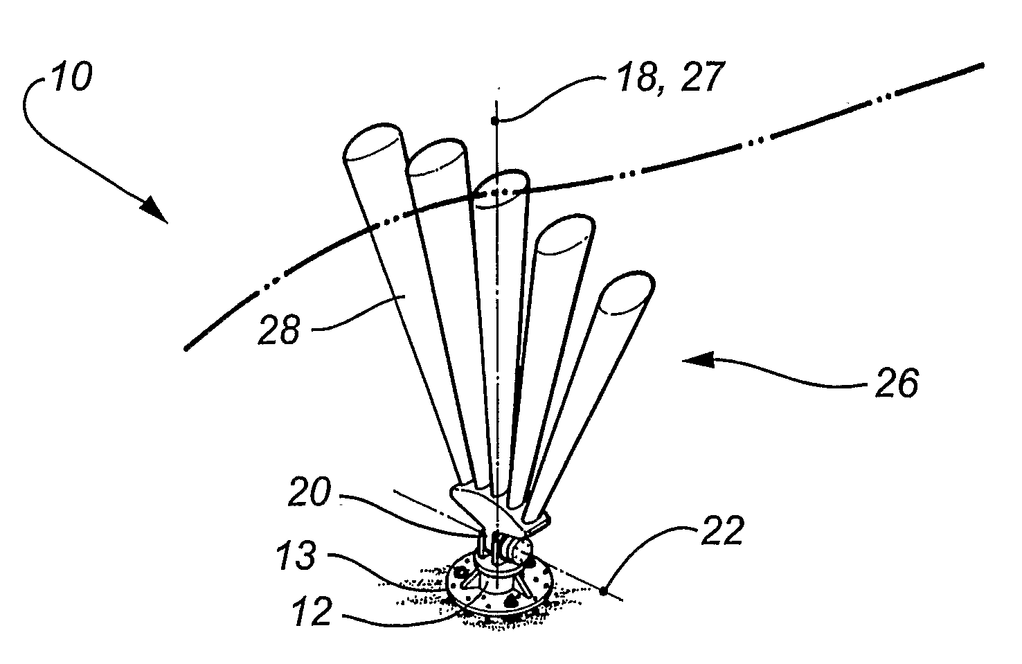
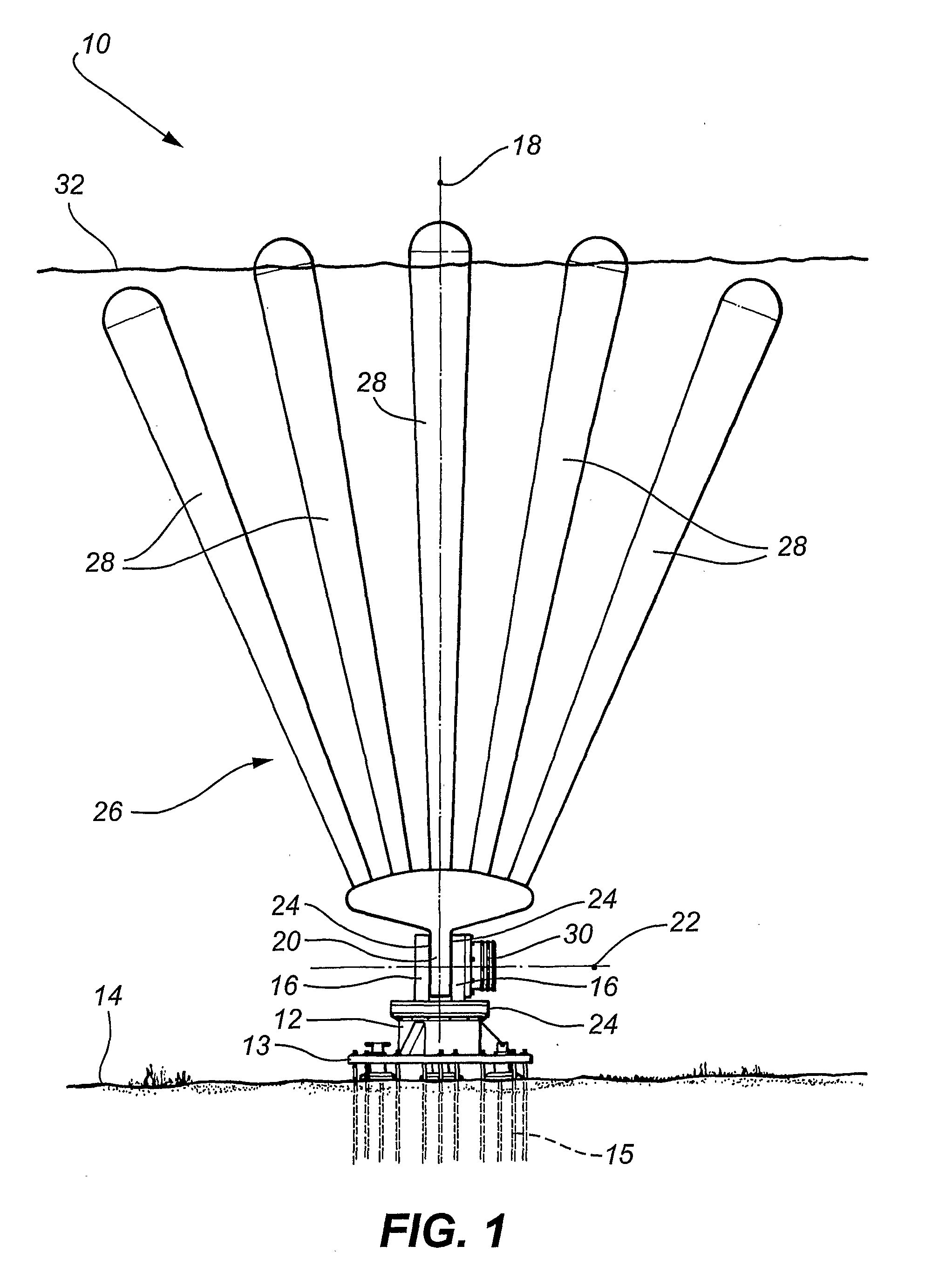
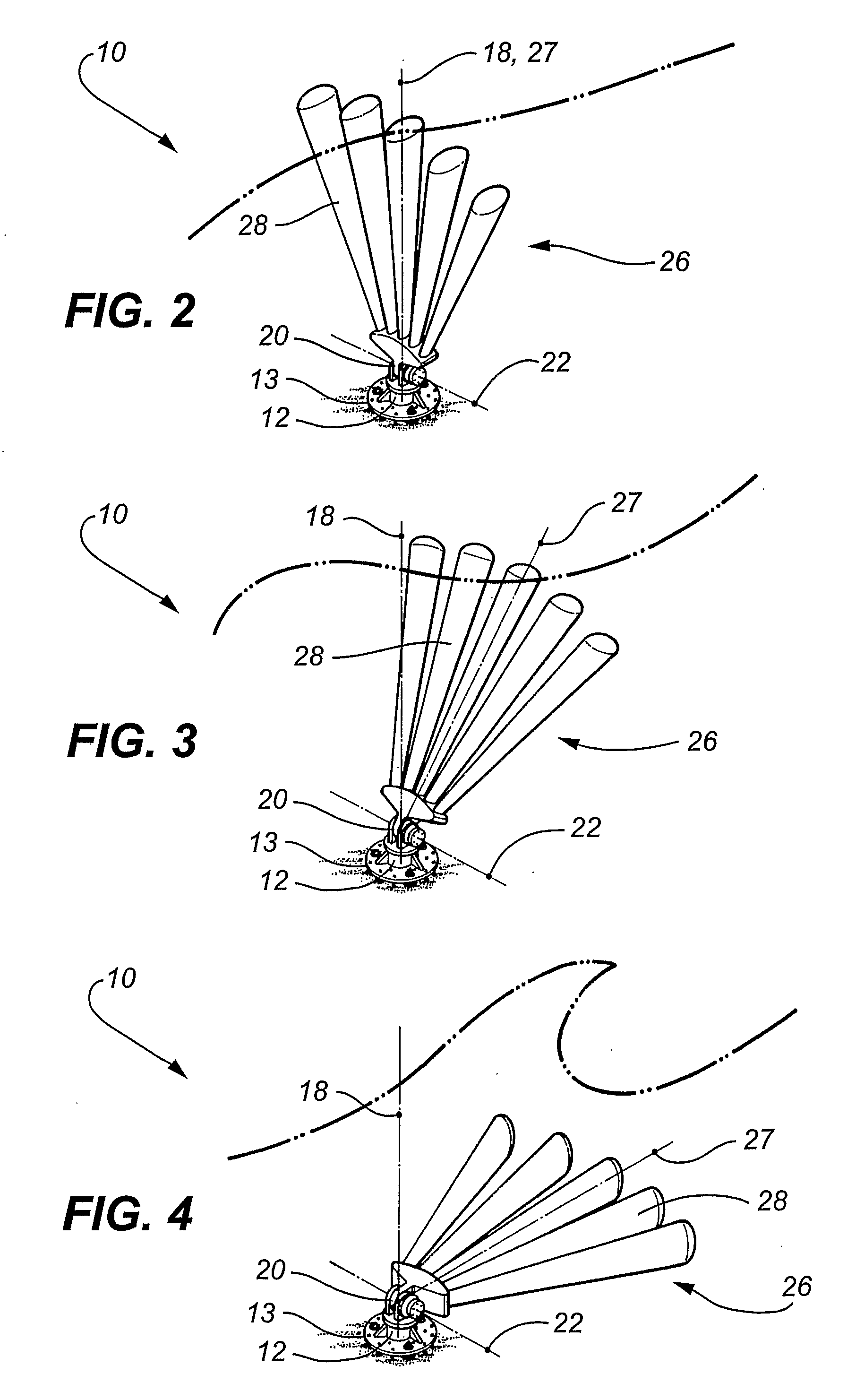
[0077]Referring to the drawings, the wave energy capturing device 10 comprises a base 12 having a circular mounting flange 13 adapted for fixed connection to a submerged surface (i.e. the seabed) 14 by a plurality of anchor bolts 15. A bracket 16 is rotatably mounted to the base 12 about a pivotal axis 18 extending generally perpendicularly (i.e. vertically) from the ocean floor 14. An axle 20 is pivotally mounted to the bracket 16 about a pivotal axis 22 extending generally parallel (i.e. horizontally) to the submerged surface 14. Water lubricated bearings 24 are provided between the bracket 16 and the base 12, as well as between the axle 20 and the bracket 16.

[0078]An elongate buoyant paddle 26, having a longitudinal axis 27 is fixedly connected at one end to the axle 20 and has an opposite free end. Accordingly, the paddle 26 is pivotable relative to the base 12 and the submerged 14 about both axes 18 and 22. The paddle 26 is adapted to angularly oscillate through an angle range ...


PUM


Abstract

A wave energy capturing device (10) comprising a base (12) adapted for fixed connection to a submerged surface (14). At least one elongate buoyant paddle (26) is pivotally mounted to the base (12) about a first pivotal axis (22), for angular oscillation through an angle range when wave motion applies a force to the paddle (26). The paddle (26) has a longitudinal axis (27), an upper end portion and a lower end portion. An energy transfer member is attached to the paddle (26) and is adapted to be driven by the angular oscillation of the paddle (26). A paddle adjustment assembly is associated with the paddle (26) and is adapted to adjust the angle range of the paddle (26) in magnitude and / or angular position relative to the first pivotal axis (22).

Description

FIELD OF THE INVENTION[0001]The present invention relates to wave energy capturing devices.[0002]The present invention has been developed primarily for use in capturing ocean wave energy for electricity generation. However, it will be appreciated that the invention is not limited to this particular application and may also be fitted with a reciprocating seawater pump to create high pressure seawater to be used for desalination or for driving other external devices.BACKGROUND OF THE INVENTION[0003]Known wave energy capturing devices include a base and a paddle pivotally connected to the base. The paddle is driven to pivotally oscillate about a generally horizontal axis, in response to ocean wave forces, to drive a generator. The paddle is typically a solid plate. The paddle has a fixed alignment, and accordingly, pivots only in a fixed plane. The paddle also maintains a fixed operative range of motion regardless of prevailing ocean conditions.[0004]The magnitude and direction of wave...

Claims


Application Information

Patent Timeline
Patent Type & Authority Applications(United States)
IPC IPC(8): F03B13/18
CPCF03B13/182F05B2220/70642Y02E10/38F05B2250/292F05B2250/71F05B2220/7068Y02E10/30
Inventor FINNIGAN, TIMOTHY DONEGAL
Owner BIOPOWER SYSTEMS PTY LTD
Why Eureka
Try Eureka