Device for Capturing Energy from a Fluid Flow

a technology of fluid flow and energy, applied in the direction of water-power plants, machines/engines, electric generator control, etc., can solve the problems of inefficient capture of energy from the water flow, inability to realign with the changing direction of water flow, and reduce the overall efficiency, so as to prevent internal corrosion or leakage

Inactive Publication Date: 2010-06-10
BIOPOWER SYSTEMS PTY LTD
View PDF8 Cites 10 Cited by
  • Summary
  • Abstract
  • Description
  • Claims
  • Application Information

AI Technical Summary

Benefits of technology

[0019]Preferably, a machine is connected to said energy transfer mechanism and is adapted to be driven thereby. The machine can preferably function both as a motor and as a generator. More preferably, said machine incorporates a synchronous permanent magnet motor/generator. In a preferred form, a stator of said motor/generator is fixedly connected to said base at an underside of said motor/generator. A rotor of said motor/generator is pref...

Problems solved by technology

A disadvantage of the device disclosed in U.S. Pat. No. 6,731,018 is that it can not realign with changing directions of water flow.
Another disadvantage of the device disclosed in U.S. Pat. No. 6,731,018 is that it inefficiently captures energy from the water flow, due to the required movement of a large tank against the resistance of the water.
Another disadvantage of the device disclosed in U.S. Pat. No. 6,731,018 is that energy from the flow is transferred to the generators in an indirect manner, having to pass through multiple intermediate stages (water to hydrofoils, hydrofoils to tank motion, tank motion to air compression, air compression to flow across turbine), which together...

Method used


Image

  • Device for Capturing Energy from a Fluid Flow
  • Device for Capturing Energy from a Fluid Flow
  • Device for Capturing Energy from a Fluid Flow

Examples


Embodiment Construction

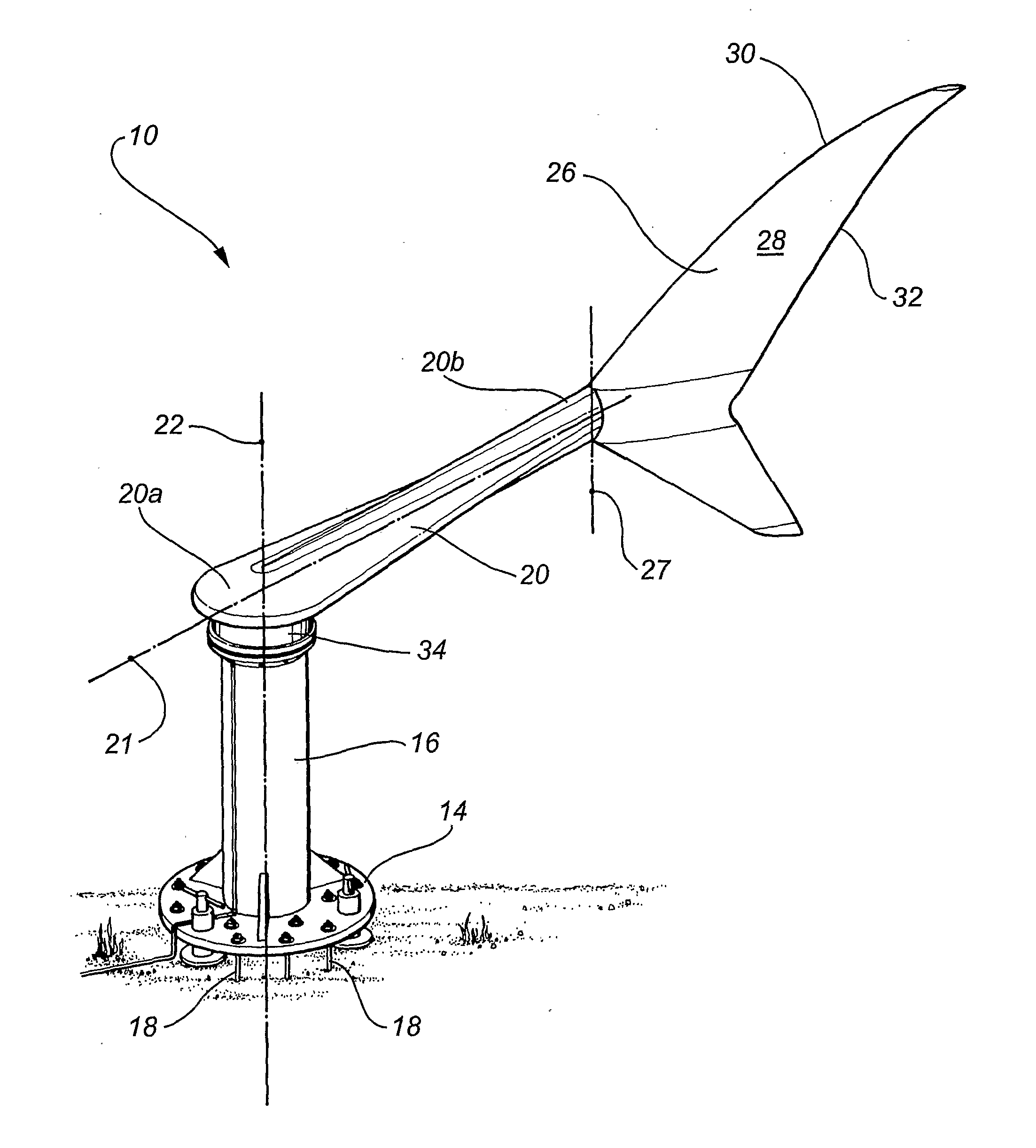
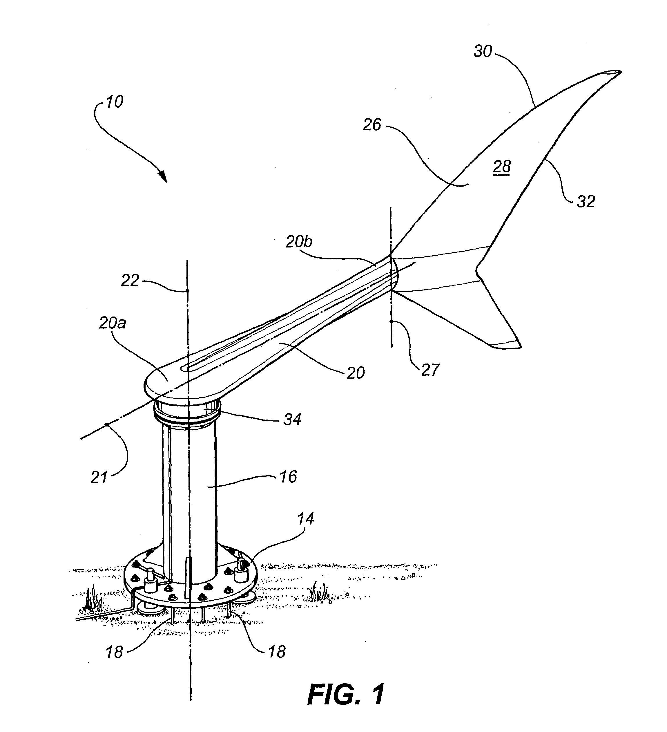
[0081]FIG. 1 shows an embodiment of a device 10 for capturing energy from a water flow, such as a tidal or marine flow or fast-flowing river. The device 10 comprises a base 12 including a generally circular mounting flange 14 and a cylindrical column 16 fixedly connected to and extending generally perpendicularly from the flange 14. The mounting flange 14 is adapted for stationary mounting relative to the water flow by a plurality of anchor bolts 18.

[0082]The base 12 forms part of a mooring for anchoring the device 10 relative to the water flow. The mooring is disclosed in detail in the Applicant's earlier filed Australian Provisional Patent Application No. 2006904030 and the co-pending international patent application claiming Convention priority therefrom, the disclosures of which are incorporated herein by reference.

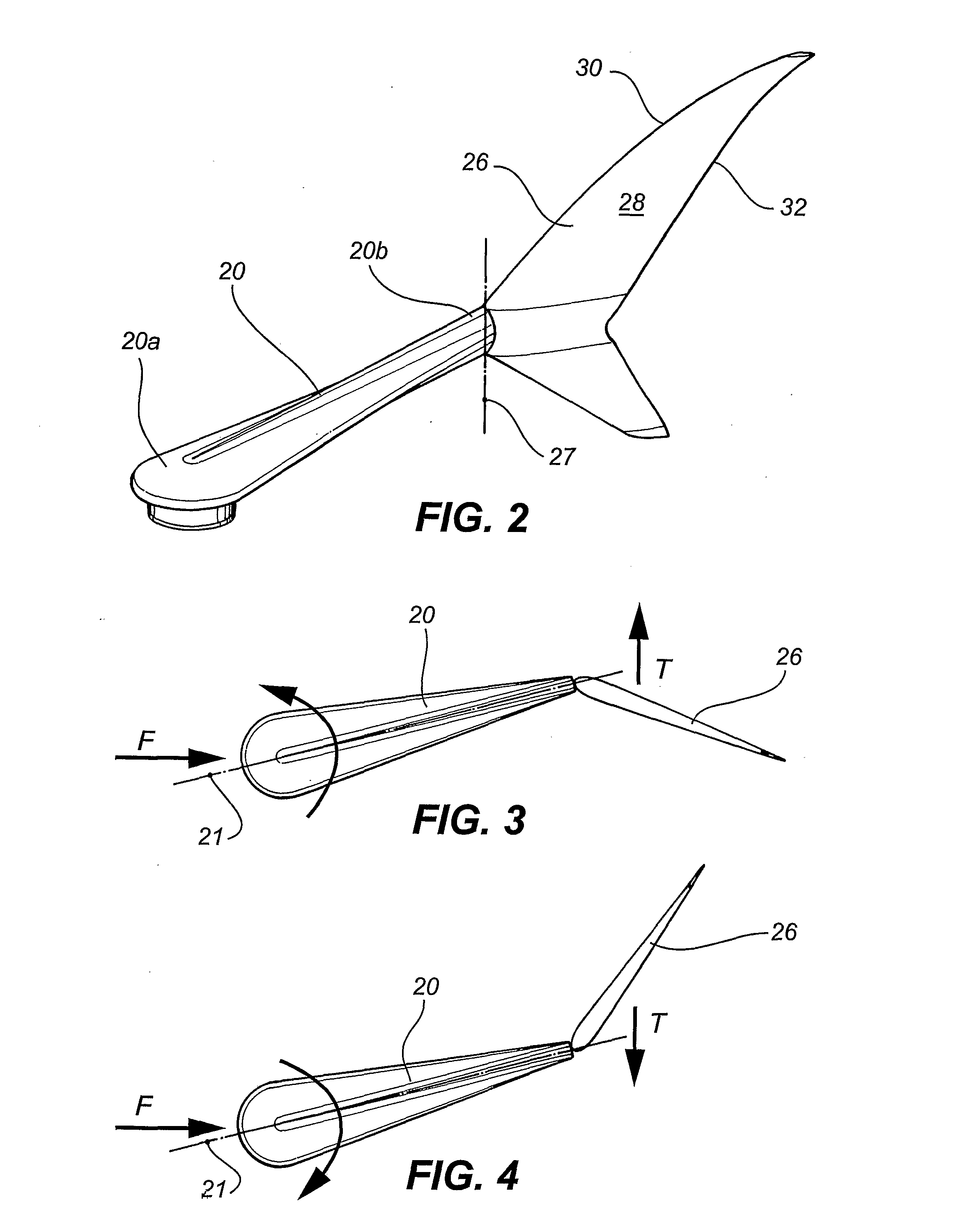
[0083]As shown in FIGS. 1 and 2, a streamlined oscillatible member 20, having a longitudinal axis 21, is pivotally connected, about a generally vertical pivotal axis ...


PUM


Abstract

A device (10) for capturing energy from a fluid flow is disclosed. The device (10) comprises a base (12) adapted for stationary mounting relative to the fluid flow. A member (20), having a longitudinal axis (21), is movably connected relative to the base (12) and is adapted to move relative to the base (12) towards a position in which the longitudinal axis (21) generally aligns with a vertical plane parallel to the direction of the fluid flow passing the member (20). A lift generating element (26) is connected to the member (20) and is movable relative to the direction of the fluid flow to vary a direction of lift produced by the lift generating element (26) as fluid flows therearound. The lift generated by the lift generating element (26) drives the member (20) in oscillatory motion relative to the base (12). An energy transfer mechanism is attached to the member (20) and is adapted to be driven by the oscillation of the member (20).

Description

FIELD OF THE INVENTION[0001]The present invention relates generally to a device for capturing energy from a fluid flow and more particularly from tidal or marine currents or fast-flowing rivers.[0002]The present invention has been developed primarily for use in hydro-electricity generation, and will be described hereinafter with reference to this application. However, it will be appreciated that the invention is not limited to this particular application and can also be used to generate electricity from wind. Also, instead of generating electricity, the device may be fitted with a reciprocating pump to create a source of high pressure water for desalination or may be adapted for driving other external devices.BACKGROUND OF THE INVENTION[0003]U.S. Pat. No. 6,731,018 discloses a device for capturing energy from tidal flows and river currents. This device includes a column fixedly mounted to the sea floor and a buoyant open bottomed tank slidably mounted on the column. Several hydrofoi...

Claims


Application Information

Patent Timeline
IPC IPC(8): F03D5/06F03B13/10H02P9/04
CPCF03B13/264F03B17/062F03D5/06Y02E10/72Y02E10/38Y02E10/70Y02E10/28Y02E10/30E02B9/08F03B13/18F03B13/26F03D5/00Y02E10/20
Inventor FINNIGAN, TIMOTHY DONEGAL
Owner BIOPOWER SYSTEMS PTY LTD
Why Eureka
Try Eureka