

Device for monitoring the temperature of an element
a technology for monitoring devices and elements, applied in the direction of instruments, heat measurement, contacts, etc., can solve problems such as inability to reverse the solution
- Summary
- Abstract
- Description
- Claims
- Application Information
AI Technical Summary
Benefits of technology
Problems solved by technology
Method used
Image

Examples
Embodiment Construction
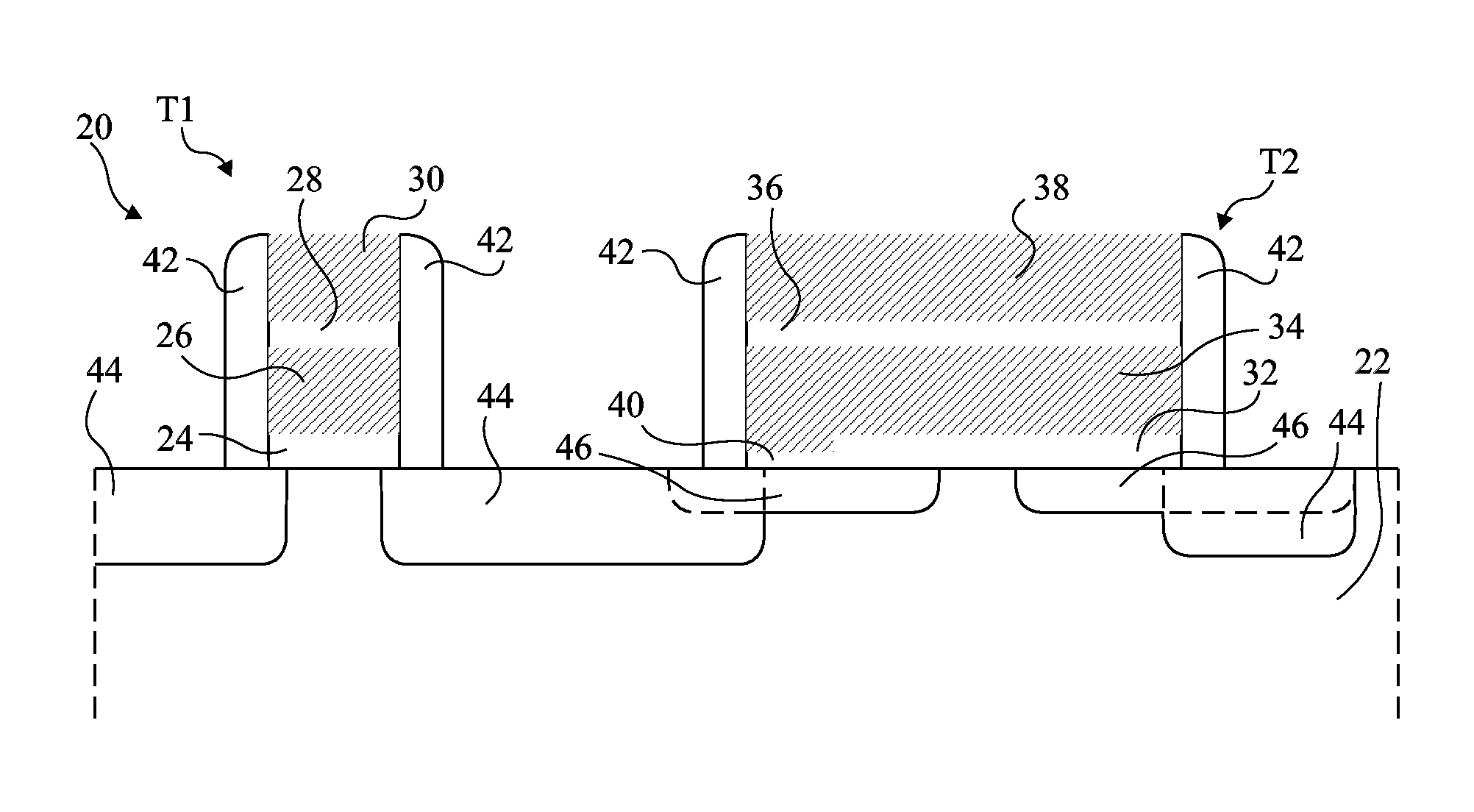
[0027]For clarity, the same elements have been designated with the same reference numerals in the different drawings and, further, as usual in the representation of integrated circuits, the various drawings are not to scale.
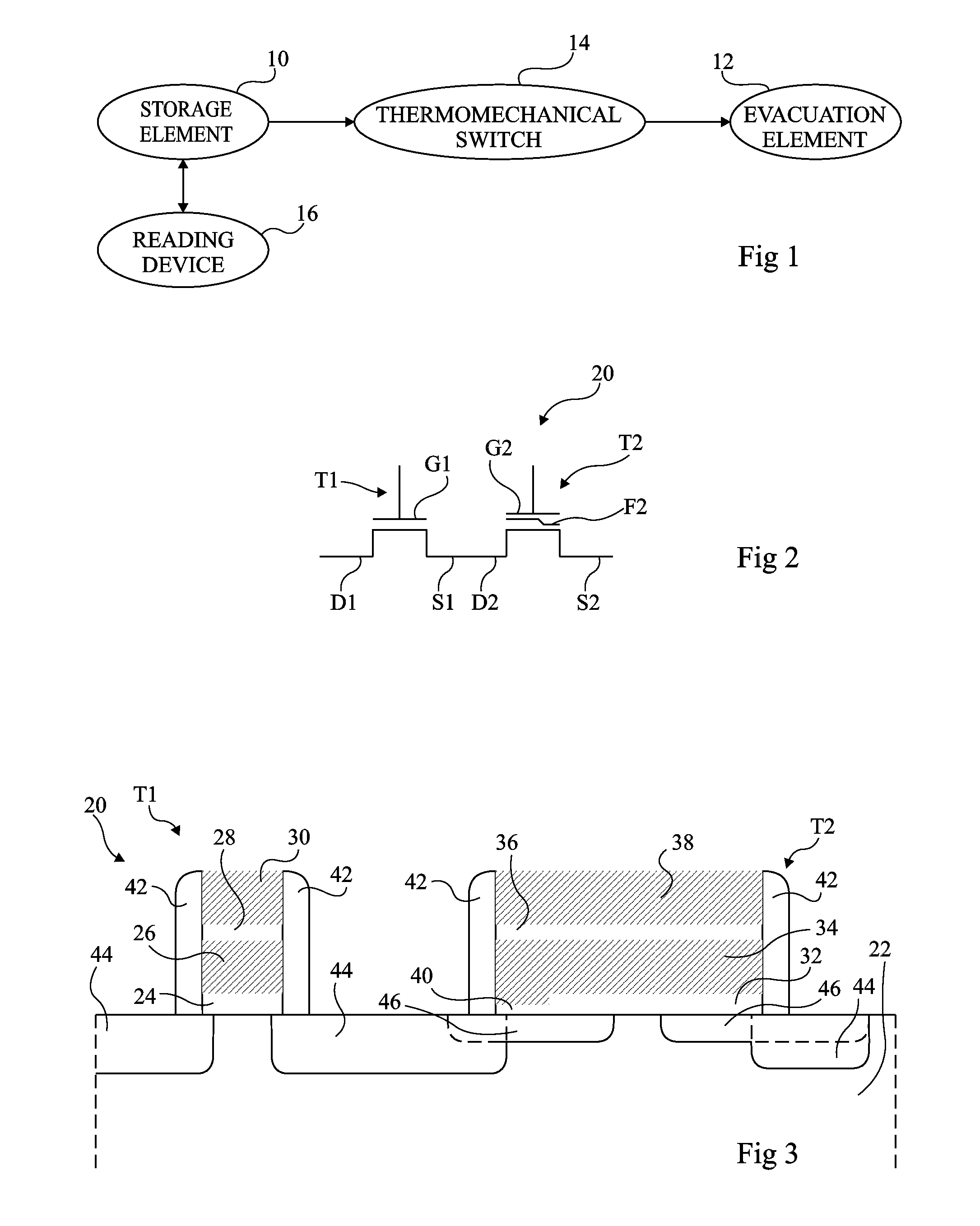
[0028]The inventors provide a circuit and a method for monitoring the temperature surrounding the circuit, requiring no continuous powering during the monitoring. Such a circuit may, for example, be used to make sure that the temperature of a product, in a transportation phase, does not exceed a threshold above which the product is altered. It may also be used to detect reverse engineering operations on a product. Indeed, such operations generally provide the steps of heating at high temperatures, which can thus be detected. It may also be desired to know the history of the temperature of a product in case a product is returned by a customer to verify that the product has been used by the customer in normal temperature conditions.
[0029]FIG. 1 is a block diagram o...
PUM
| Property | Measurement | Unit |
|---|---|---|
| temperatures | aaaaa | aaaaa |
| length | aaaaa | aaaaa |
| temperature | aaaaa | aaaaa |
Abstract
Description
Claims
Application Information