
Wide-band signal processor

a signal processor and wide-band technology, applied in the field of digital signal processor and method for processing input signals, can solve the problems of increasing the number of input signal samples, increasing power consumption, and complex processing of input signals

Active Publication Date: 2010-06-24
STMICROELECTRONICS SRL
View PDF6 Cites 6 Cited by
  • Summary
  • Abstract
  • Description
  • Claims
  • Application Information

AI Technical Summary

Benefits of technology

"The present invention provides a signal processor for processing a digital input signal by dividing it into two frequency bands, shifting the second frequency band to a lower cut-off frequency, and performing decimation on the first frequency band to generate a high-resolution signal. This allows for improved processing of the digital input signal, such as improved speech quality in a communication device. The technical effects of this invention include improved signal quality, reduced echo during speech, and improved speech quality in a communication device."

Problems solved by technology

However, this leads to an increase in the number of the samples generated for the input signal, and thus processing the signal becomes more complex.
This in turn leads to higher power consumption, and more demand in terms of silicon area of the processing circuitry.

Method used


Image

  • Wide-band signal processor
  • Wide-band signal processor
  • Wide-band signal processor

Examples


Embodiment Construction

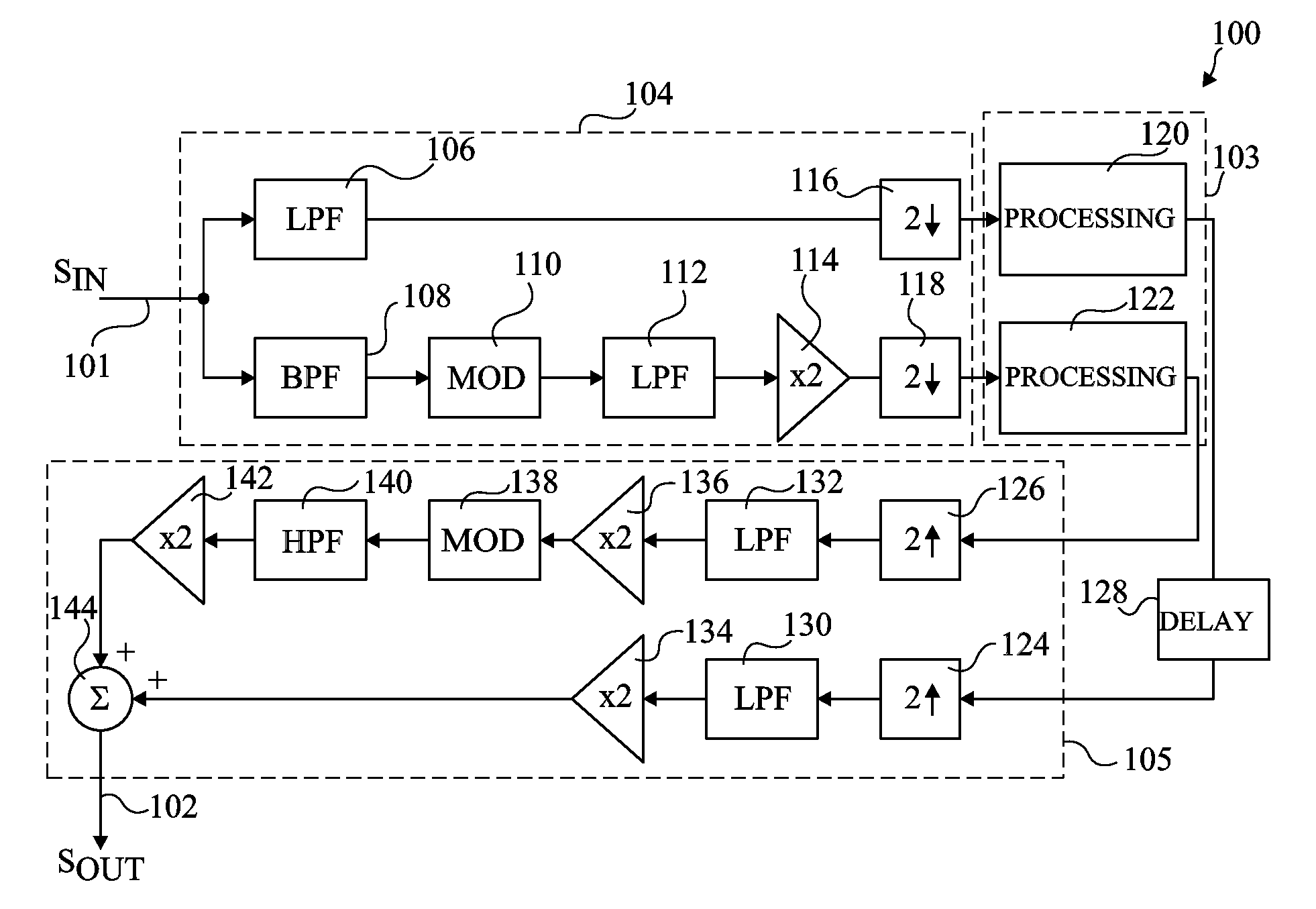
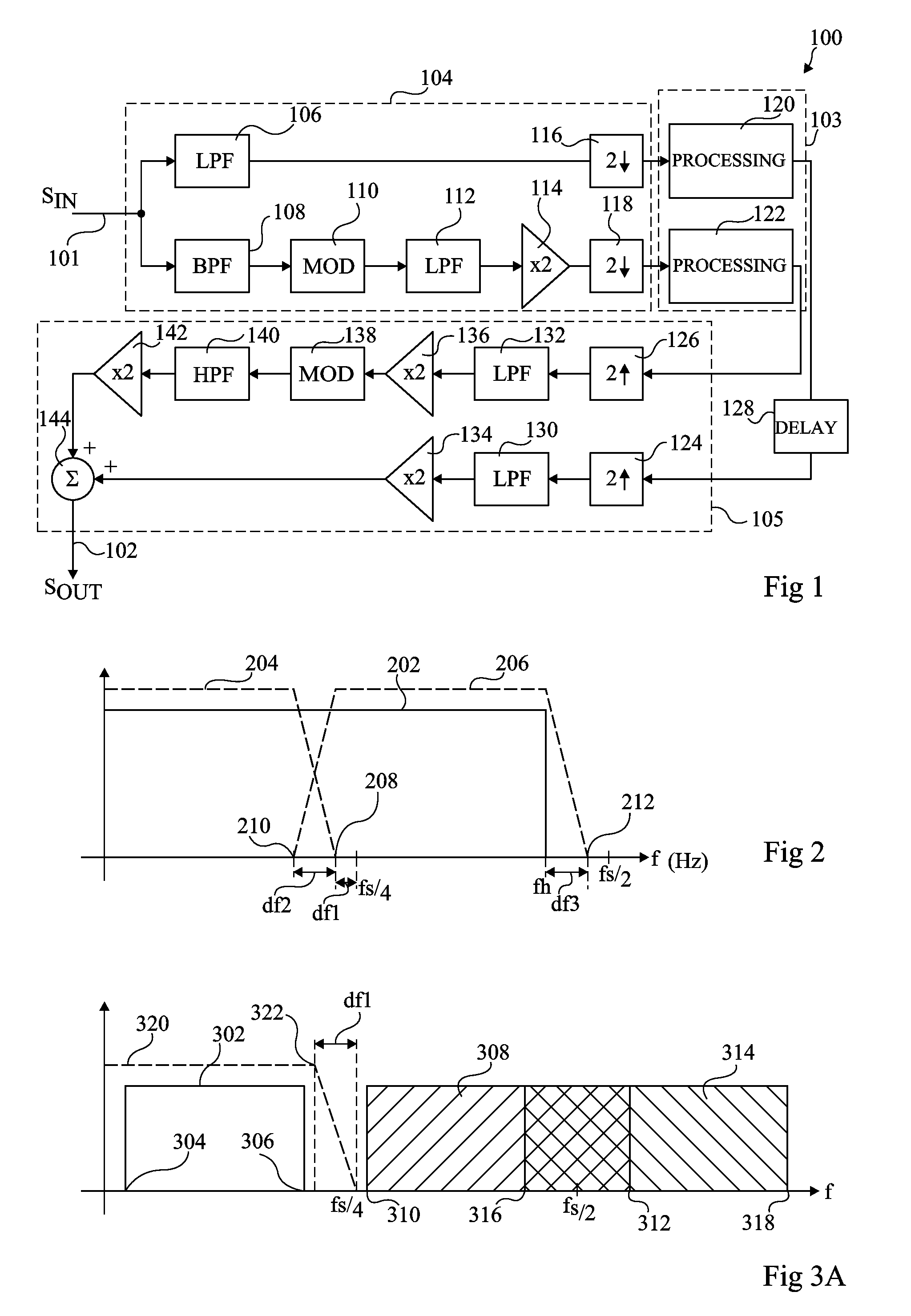
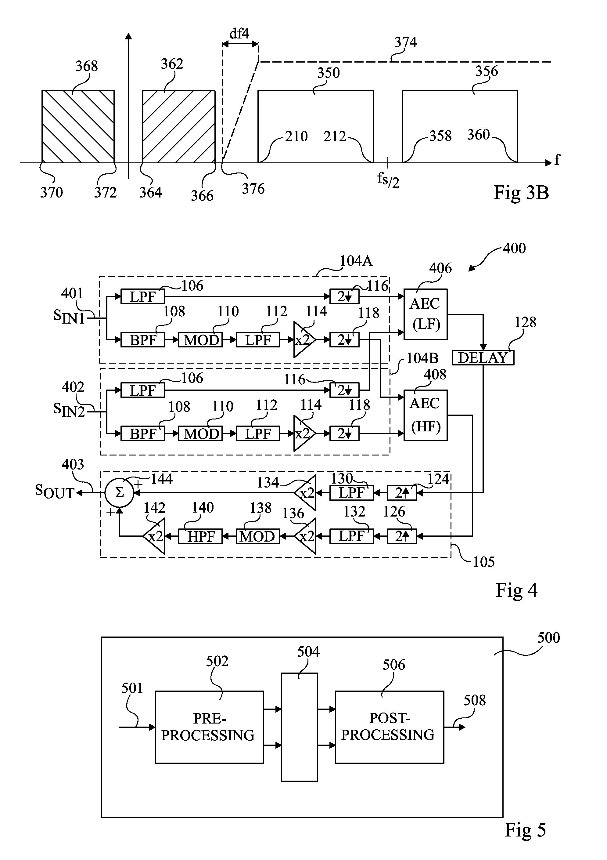
[0028]FIG. 1 illustrates a digital signal processor 100, comprising an input line 101 for receiving a digital input signal SIN, and an output line 102 for providing a digital output signal SOUT. The signal processor 100 further comprises processing circuitry 103 for processing the input signal SIN to generate the output signal SOUT. The input signal SIN is first processed by pre-processing circuitry 104 before being provided to processing circuitry 103, and signals generated by processing circuitry 103 are processed by post-processing circuitry 105 before being output as the signal SOUT.

[0029]The input signal SIN for example relates to an audio signal and comprises digital samples corresponding to a sampling rate fs, which is for example in the range 8 kHz to around 200 kHz, and for example at 16 kHz. For example, the input signal results from digitally sampling an analog signal at over twice the Nyquist frequency, the digital sample for example being provided directly to the input ...


PUM


Abstract

A signal processor for processing a digital input signal including samples sampled at a sampling frequency, the signal processor comprising a plurality of filters arranged to divide the digital input signal into a first signal in a first frequency band below a first cut-off frequency, and a second signal in a second frequency band above a second cut-off frequency; first frequency shifting circuitry arranged to shift the second signal to a frequency band below the first cut-off frequency; decimation circuitry arranged to decimate the first signal and the shifted second signal; and processing circuitry arranged to process the decimated first and second signals.

Description

CROSS REFERENCE TO RELATED APPLICATIONS[0001]This application claims the priority benefit of French patent application No. 08 / 59019, filed on Dec. 23, 2008, entitled “WIDE-BAND SIGNAL PROCESSOR,” which is hereby incorporated by reference to the maximum extent allowable by law.BACKGROUND OF THE INVENTION[0002]1. Field of the Invention[0003]The present invention relates to a digital signal processor and method for processing an input signal, in particular a wide-band input signal.[0004]2. Discussion of the Related Art[0005]In digital signal processing systems, analog input signals are generally sampled at twice the Nyquist frequency, in other words at twice the bandwidth of the signal, to convert them into digital signals. Increasing the sampling frequency therefore also increases the bandwidth of the signal that can be recovered.[0006]Wide-band signals have a larger bandwidth that normal signals, and are thus sampled at a higher frequency. However, this leads to an increase in the nu...

Claims


Application Information

Patent Timeline
Patent Type & Authority Applications(United States)
IPC IPC(8): H04L27/14
CPCH03H17/0266G10L19/0204
Inventor MENU, MICHELBOURMEYSTER, IVAN
Owner STMICROELECTRONICS SRL
Learn More