Self-Counter-Sinking Screw with Circumferential Cutters

a self-countersinking screw and cutter technology, which is applied in the direction of screws, threaded fasteners, and fastening means, etc., can solve the problems of raising a dimple in the veneered surface, unable to bury the screw head below the surface of cement board, and the underside of the screw head tends to tear the film

Active Publication Date: 2010-06-24
ILLINOIS TOOL WORKS INC
View PDF20 Cites 35 Cited by
  • Summary
  • Abstract
  • Description
  • Claims
  • Application Information

AI Technical Summary

Benefits of technology

The present invention is a screw design that includes a frustoconical shoulder with inset triangular recesses and cutting edges, acting as a countersink device. The recesses form pockets that contain scarified debris from the countersinking action. The peripheral ring of cutters are arranged outwardly from the countersink pockets. Each triangular cutter has specialized cutting facets that create multiple cutting edges adapted to cut into a hardened plastic surface such as Melamine. The correlation of the pockets adjacent the cutters allows the debris from cutting to be ejected or trapped in the pockets, and facilitates the full, flush penetration of the screw head into the plastic veneered surface without causing dimpling, buckling or mushrooming of the surface. The screw is more stable as it cuts and countersinks, due in part to the plurality of cutting surfaces balancing out lateral pressures. The present invention virtually eliminates the need for a pilot hole, reducing the risk of damage to the workpiece.

Problems solved by technology

The technical problem addressed in this patent is the difficulty of installing screws into plastic veneered substrates without creating cracks or dimples in the surface, and the difficulty of installing screws into cement board without the need for a pilot hole. The invention proposes a self-countersinking screw that solves these problems.

Method used


Image

  • Self-Counter-Sinking Screw with Circumferential Cutters
  • Self-Counter-Sinking Screw with Circumferential Cutters
  • Self-Counter-Sinking Screw with Circumferential Cutters

Examples


Embodiment Construction

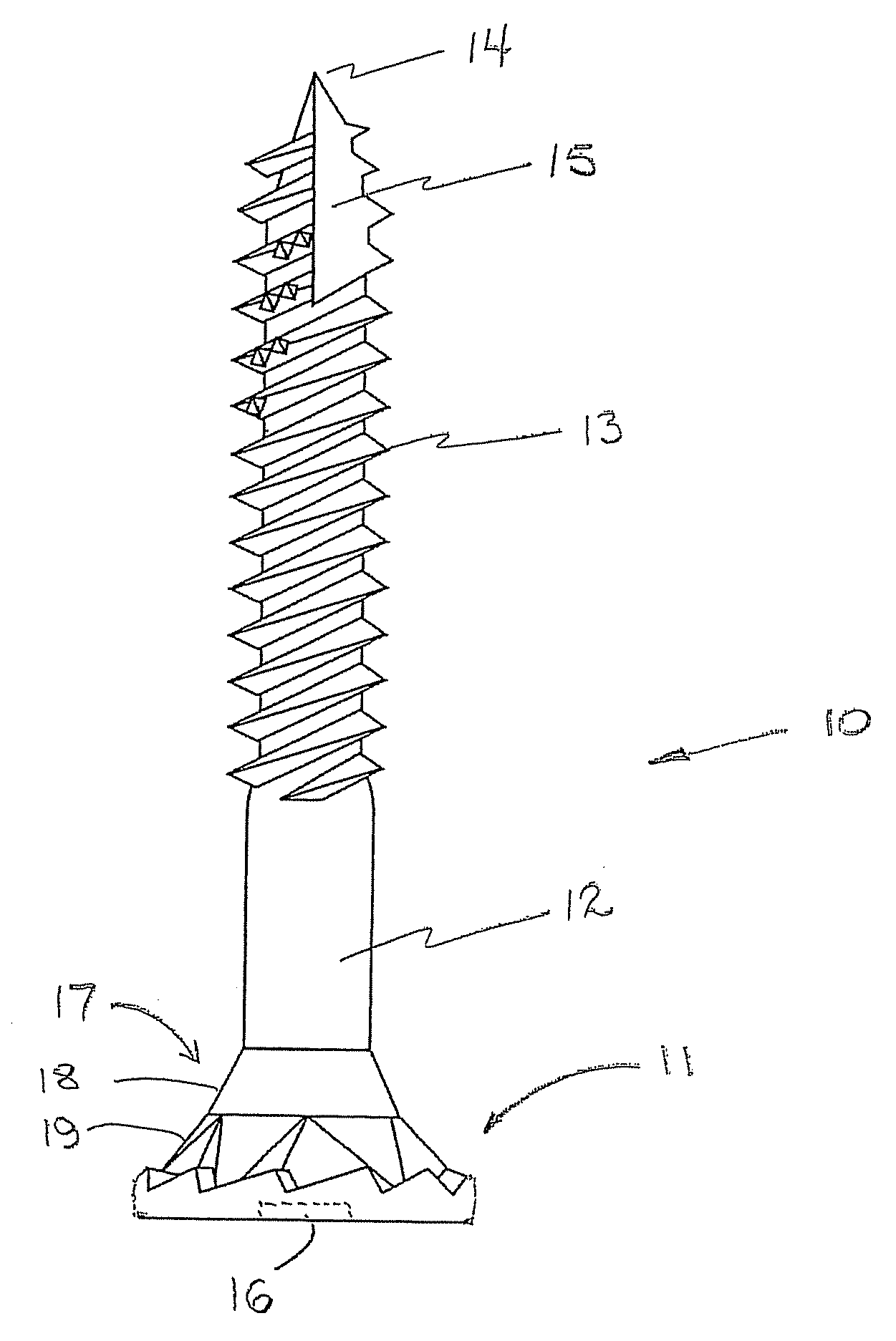
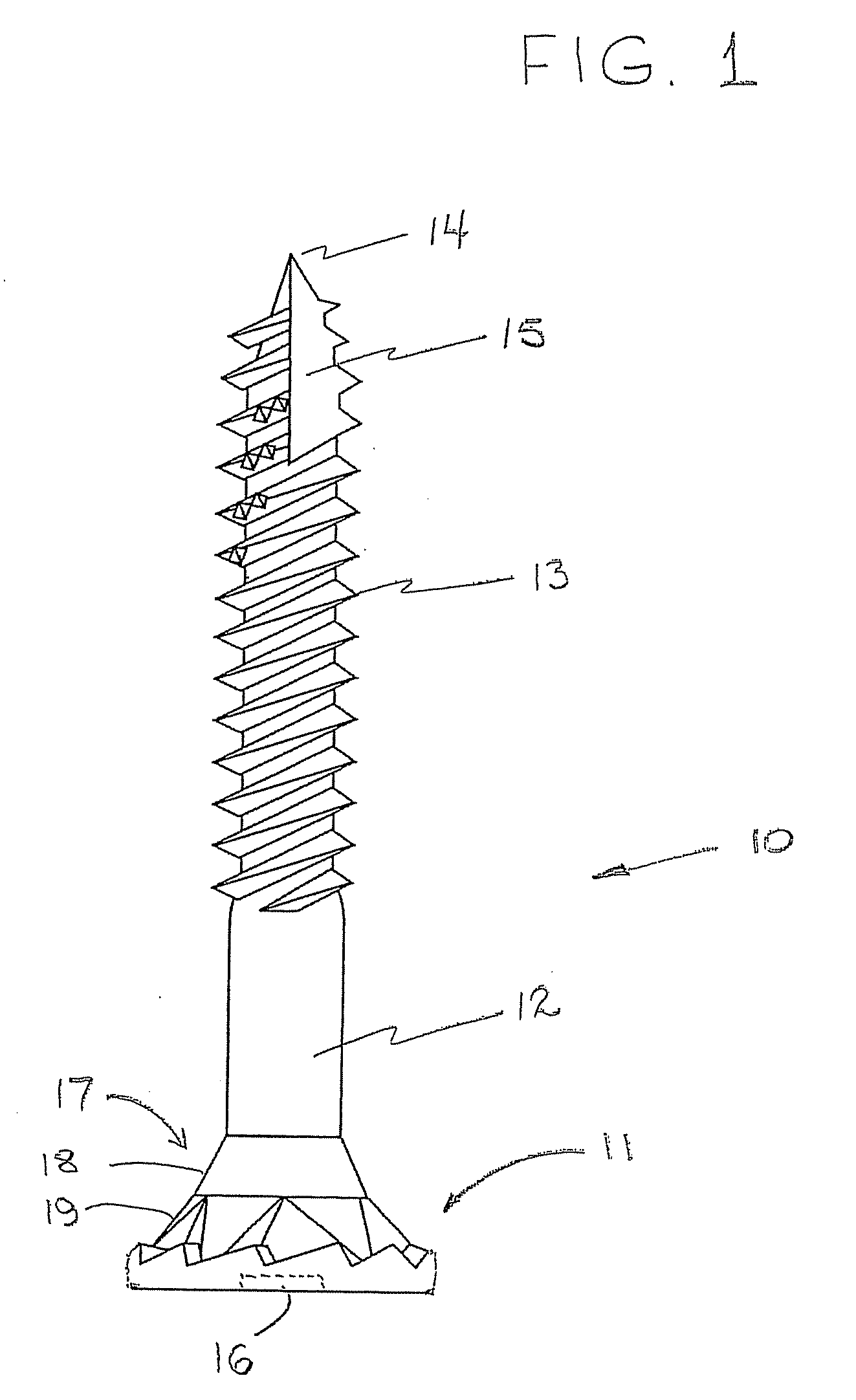
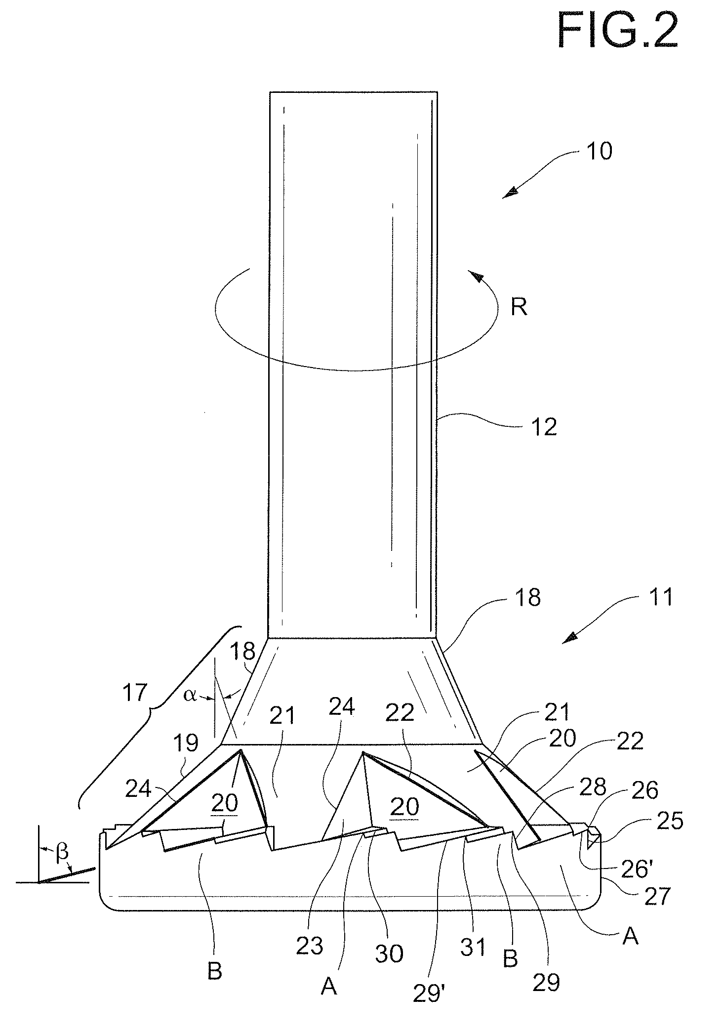
[0020]With reference to the drawings, and in particular to FIGS. 1 and 2 thereof, the self-countersinking screw 10 comprises a head 11 and a shank 12 with threads 13 ending in a tip 14. Penetration of the screw into the workpiece may be aided by a gimlet or Speedtip™ notch 15. The head 11 has a generally conical shape, with the top of the screw head having a screw driver engaging means 16 adapted to receive the tip of a screwdriver (not shown) or other driving means. It should be noted that the screwdriver engaging means may be any suitable shape including slot, Allen / hex, Phillips, Robertson, or Torx, (as illustrated in FIG. 3).

[0021]The underside of the head 11 connects to the shank 12 by a generally frustoconical shoulder 17. In the embodiment illustrated in FIGS. 1 and 2, the frustoconical shoulder 17 comprises two frustoconical portions having different tapers, namely a first shoulder portion 18 and a second shoulder portion 19. However, a single frustoconical shoulder may be e...


PUM

PropertyMeasurementUnit
Angleaaaaaaaaaa
Lengthaaaaaaaaaa
Radiusaaaaaaaaaa

Abstract

A self-countersinking screw (10) is capable of full penetration into wood, plastic veneered wood, and cementaceous products. An alternating sequence of peripheral cutters (A, B) extend from the periphery of the underside of the screw head (11), acting in conjunction with countersink cutting edges (24) and debris receiving recesses (20). Cutter (A) has an arcuate notch (30) in the cutting face (28), cutter (B) has a rectangular notch (31) in the trailing edge. Full countersinking without tearing, cracking or dimpling of the surface is achieved.

Description


Claims


Application Information

Patent Timeline
Owner ILLINOIS TOOL WORKS INC
Why Eureka
Try Eureka