Apparatus for separating parts

a technology for separating parts and apparatuses, applied in the direction of absorbent pads, conveyers, articles, etc., to achieve the effect of simple and reliable apparatus design and compact structur

Inactive Publication Date: 2010-06-24
ROMACO PHARMATECHN
View PDF7 Cites 8 Cited by
  • Summary
  • Abstract
  • Description
  • Claims
  • Application Information

AI Technical Summary

Benefits of technology

[0012]In another particularly advantageous embodiment, several transverse guide tracks are provided which are adjustable for movement along the longitudinal guide tracks with different speeds. In this way, several parts disposed behind one another can be transported at the same time, which advantageously affects the cycle time of the apparatus.
[0013]In a four transverse guide track arrangement parts may for example be picked up and deposited by the holding elements at the same time, wherein during pick-up or respectively deposit of the parts, the transverse guide track by which the parts had been picked up, can be moved from the first to the second position and the transverse guide track, which had deposited the parts, can be moved from the second position to the first position. It is in this connection particularly advantageous that the holding elements can be adapted during pick up and during deposit of the parts, to the speed of the elements from which the parts are picked up or on which the parts are deposited. The elements can therefore be moved continuously. For pickup, the parts do not need to be spaced from one another.
[0014]In connection with the last-mentioned embodiment, it is particularly advantageous if the transverse guide track is mounted to hollow shafts which provides for a very compact apparatus design.
[0015]In a further special embodiment of the invention, the holding elements are connected to telescopic vacuum lines via which the holding elements can be evacuated. By way of the telescopic vacuum lines a vacuum can be generated at the holding elements in a simple and reliable manner. In this way, the parts can be rapidly and reliably and still carefully picked up by the holding elements.

Problems solved by technology

This is disadvantageous in particular if the parts are arranged directly adjacent one another without any spacing, but it is necessary for the further treatment or handling of the parts that there is a space between adjacent sides of the parts.

Method used


Image

  • Apparatus for separating parts
  • Apparatus for separating parts
  • Apparatus for separating parts

Examples


Embodiment Construction

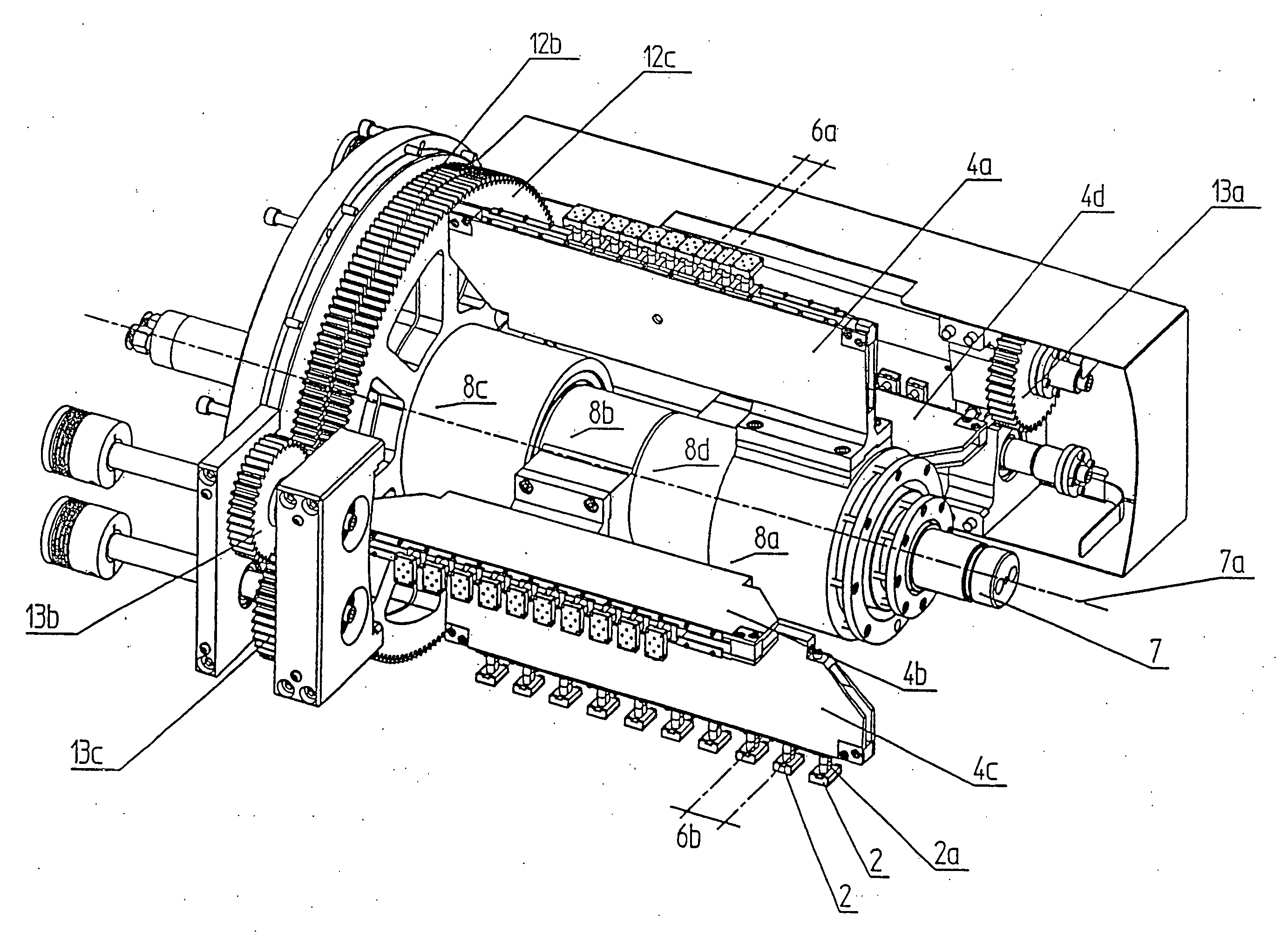
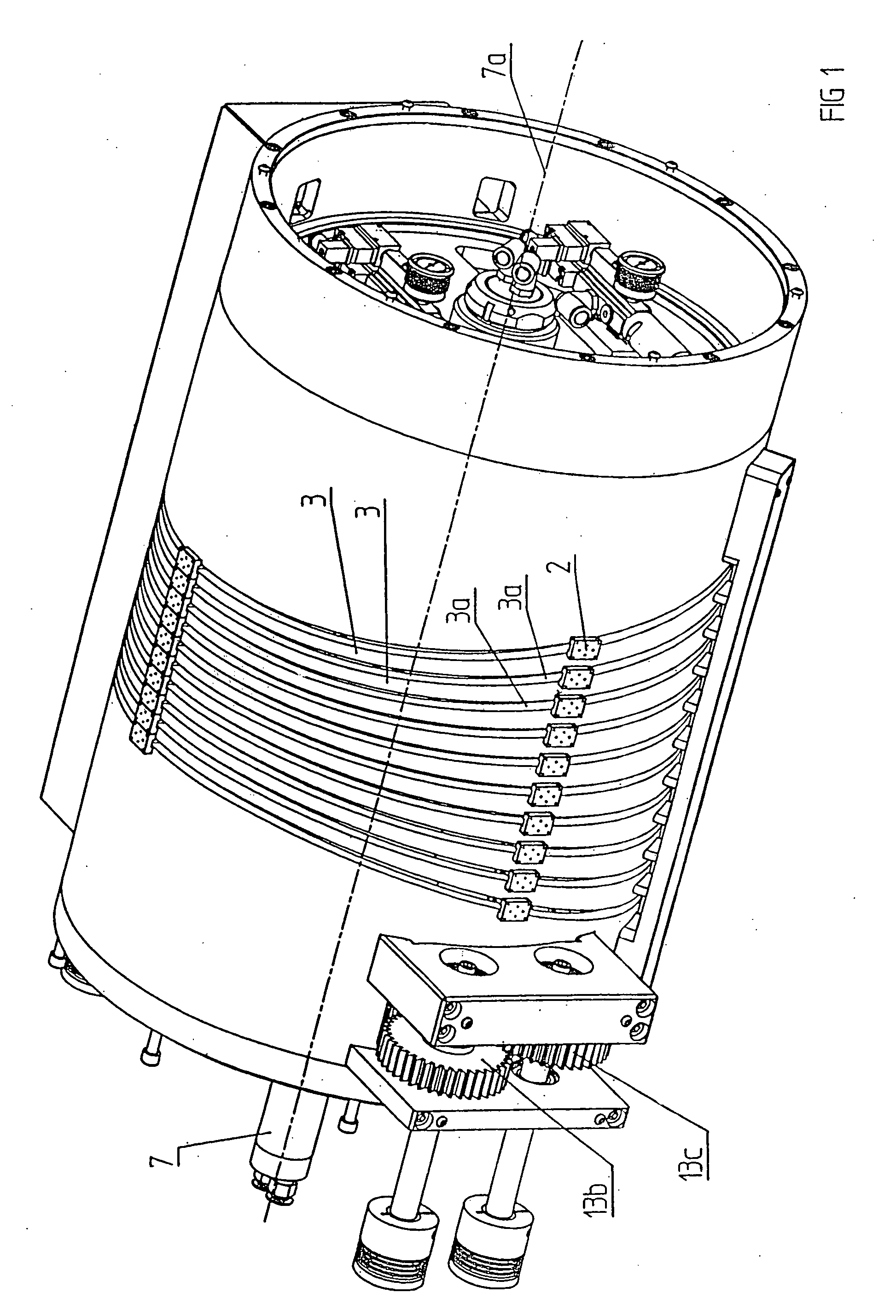
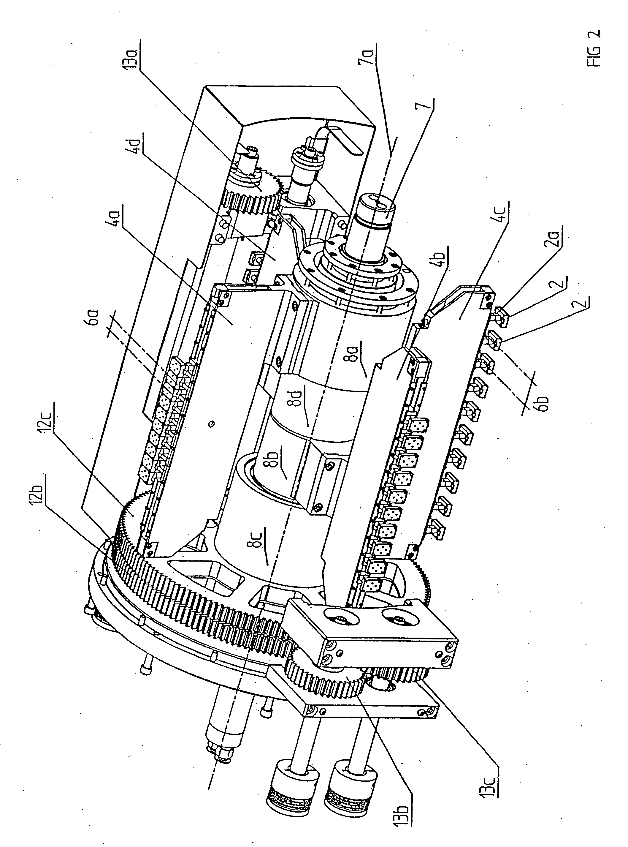
[0023]As apparent in particular from FIGS. 1 to 3, a separating apparatus according to the invention includes holding elements in the form of vacuum suction devices 2 wherein in the present case ten vacuum suction devices 2 are arranged next to one another. The vacuum suction devices 2 are arranged on carriages which are movably supported in a groove of a transverse guide track 4a to 4d and are in communication with the vacuum suction devices 2 via neck portions 2a. With the movable support of the vacuum suction devices 2 by the transverse guide tracks 4a to 4d, the lateral distance 6a, 6b at which the vacuum suction devices 2 are arranged next to one another, that is the distance 6a, 6b between the center lines of the vacuum suction devices 2, can be changed.

[0024]The transverse guide tracks 4a to 4d are each mounted to a hollow shaft 8a-8d, which is disposed on a drive shaft 7 that is rotatable about an imaginary axis 7a. The vacuum suction devices 2 are therefore movable along a ...


PUM

PropertyMeasurementUnit
distanceaaaaaaaaaa
speedsaaaaaaaaaa
vacuumaaaaaaaaaa

Abstract

In an apparatus for separating parts arranged for example in at least two adjacent rows and including a transfer device, which is provided with at least two holding elements which pick up the parts in a first position and deposit them in a second position 5b, means are provided by which the distance at which the holding elements are disposed adjacent one another is changeable during the transport of the parts from the first position to the second position.

Description

BACKGROUND OF THE INVENTION[0001]The invention resides in an apparatus according to the preamble of claim 1 for separating for example parts arranged in at least two adjacent rows, including a transfer element having at least two retaining elements arranged side-by-side which engage parts in a first position and then deposit them in a second position.[0002]Such apparatus are well-known in the art. They generally include an element which is rotatable about an axis and which is provided with several radially extending arms which are arranged side-by-side at a uniform angular distance from one another and which are provided at their ends with vacuum suction means. With the known apparatus, for example parts disposed on adjacently arranged transport belts can be grasped; pivoted by 90° or 180° and transferred to a downstream machine element.[0003]The arms of the known separating apparatus are arranged firmly on a rotatable element in side-by-side relationship so that the distance at whi...

Claims


Application Information

Patent Timeline
Patent Type & Authority Applications(United States)
IPC IPC(8): B65G47/32
CPCA61F13/15601A61F13/15764B65G47/26B65G47/914B65H2406/34525B65H29/241B65H39/14B65H2301/4481B65G47/918
Inventor KONSTANDIN, HORSTHERBACH, MATHIASKRAZMEIER, JURGENBIPPUS, JORG-UWE
Owner ROMACO PHARMATECHN
Why Eureka
Try Eureka