Pumping/nursing bra

a breast pump and nursing bra technology, applied in the field of breast pumping/nursing bra, can solve the problems of nursing mothers not having the full use of both hands to perform other tasks, and it is difficult to operate the breast pump, so as to facilitate the operation of the flange and allow the nursing mother to remove the flang

Active Publication Date: 2010-06-24
SIMPLE WISHES
View PDF33 Cites 39 Cited by
  • Summary
  • Abstract
  • Description
  • Claims
  • Application Information

AI Technical Summary

Benefits of technology

[0014]The present invention is directed to a stylish bustierre creating a tight seal between the woman's breasts and the flange shield of the breast pump. The bustierre is provided with two side panel portions, each having top and bottom elastic edges to prevent the bustierre from slipping down, as well as supporting the woman's breasts. An adjustable strap is attached to both sides of the bustierre. In one embodiment, the strap is hooked to the top front edges of both side panel portions and extends around the back of the neck of the woman for added security. Other embodiments would utilize two straps, each strap attached to the front and rear portions of one of the side portions. Each side panel portion is provided with holes corresponding to each of the woman's breasts that would easily allow a woman to insert and remove the flange shield before and after pumping. Each of these holes could be surrounded by an elastic piece, and is provided with four circular pieces as will be subsequently explained.
[0016]In yet another embodiment, a back panel and a center panel will be removably attached to the two side portions to allow the woman to adjust the fit of the pumping / nursing bra. In a further embodiment, the front center panel and the straps, as well as the back panel, can be eliminated.
[0017]In still a further embodiment, a cover panel would be provided for covering the front of the side panels, allowing the bustierre to be worn all day long.

Problems solved by technology

To express milk from both breasts, the woman must hold the breast flange or shield with each hand against her breast, leaving her in an awkward position, making it difficult to do something as simple as operating the breast pump.
As a result, the nursing mother will not have the full use of both hands to perform other tasks.

Method used


Image

  • Pumping/nursing bra
  • Pumping/nursing bra
  • Pumping/nursing bra

Examples


Embodiment Construction

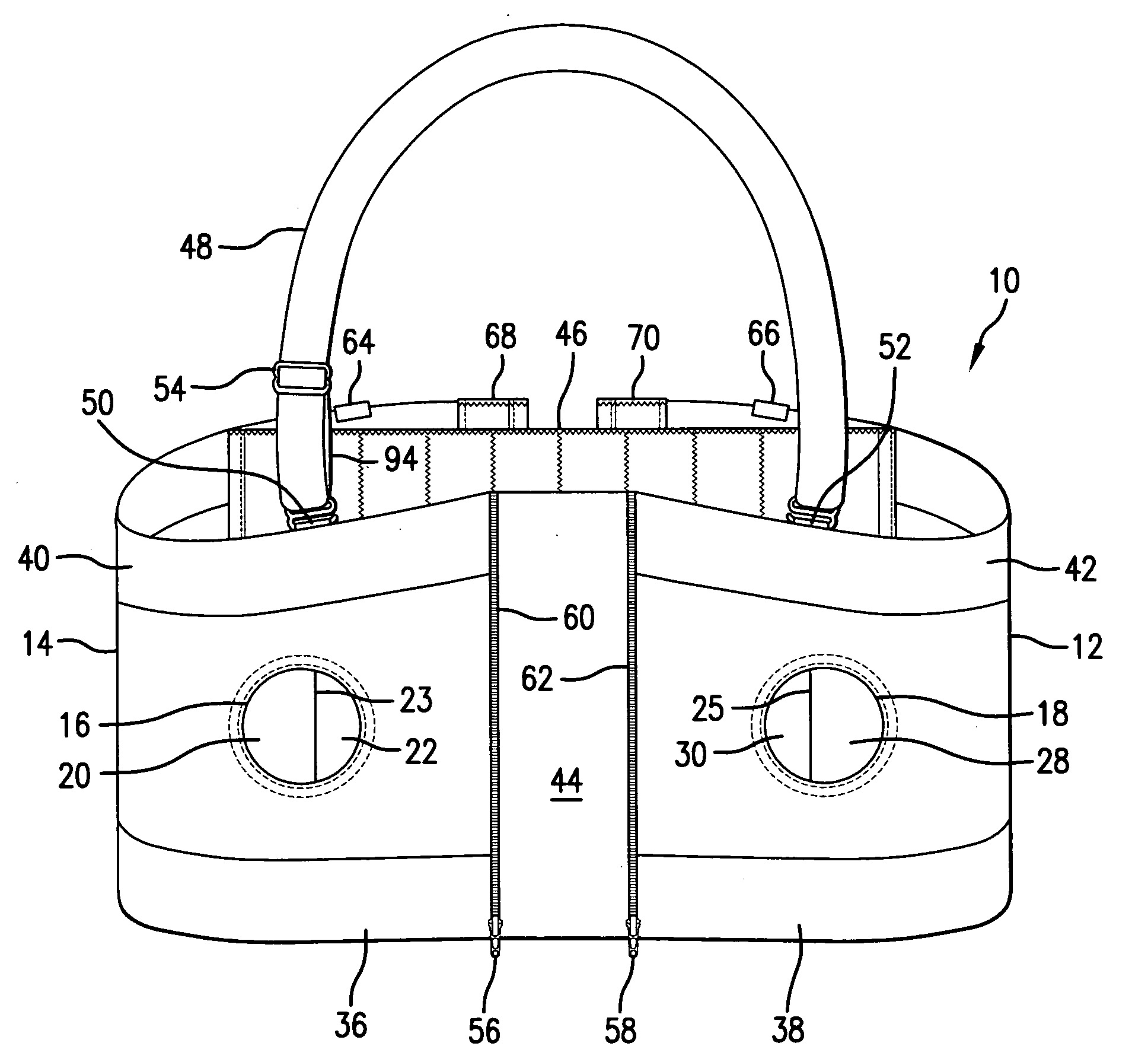
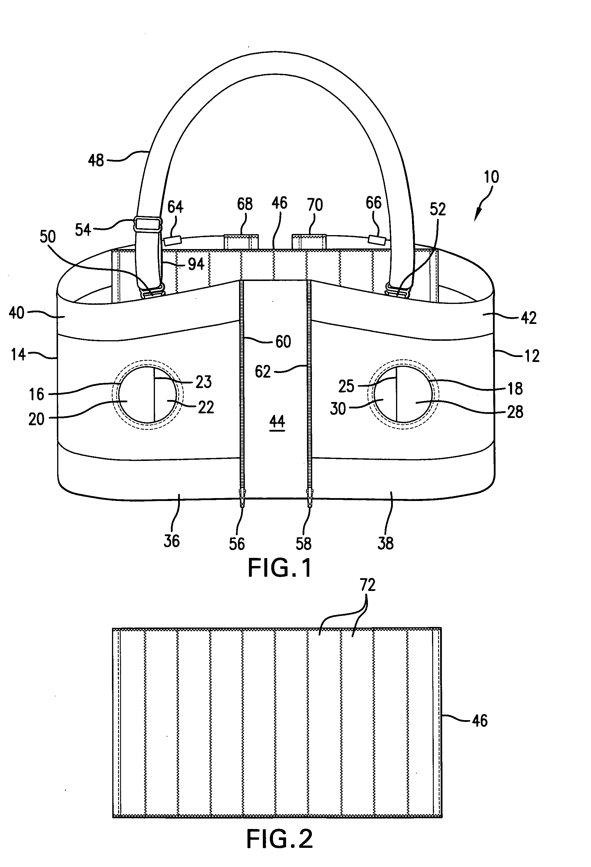
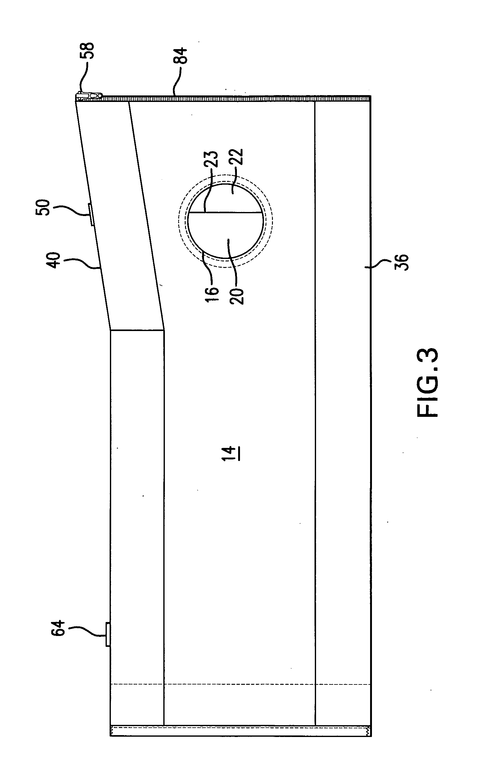
[0031]The present invention is illustrated in the drawings where like elements are assigned the same reference numerals. As shown in FIG. 1, the present invention 10 is provided with a left planar panel 12 and a right planar panel 14. The left panel 12 is constructed from a stretchable fabric portion extending for the entire length of the panel 12. A top elastic portion 42, as well as a bottom elastic portion 38, extend along the periphery of the panel 12, with both elastic portions 38, 42 running for the entire length of the left panel 12. The left panel 12 is also provided with an opening 18 through which a standard breast shield or flange would be provided against the woman's breasts. One side of the left panel 12 is provided with one-half of the teeth 78 of a standard zipper, as shown in FIG. 5. The rear side of the left panel is provided with a Velcro® portion 70 running the entire width of the left front panel 12, as shown in FIG. 6, the purpose of which will be explained here...


PUM


Abstract

An apparatus allowing a woman to pump milk from her breasts without the necessity of the woman's hands holding the breast pumps utilizes at least one band of material encircling the woman's chest, the band of material provided with two openings corresponding to the woman's breasts. A center panel would be provided to adjust the fit of the band. Additionally, in another embodiment, a back panel would be used in conjunction with the center panel to connect left and right panels together, the left and right panels including openings for a woman's breast. In all of the embodiments, semicircular pieces would cover each of the openings. In yet another embodiment, a removable piece is attached to the front of the apparatus, allowing the woman to wear the apparatus all day, even in public.

Description

CROSS-REFERENCE TO RELATED APPLICATION[0001]The present application claims the priority date of U.S. Provisional Patent Application Ser. No. 61 / 193,731, filed Dec. 19, 2008, as well as U.S. patent application Ser. No. 12 / 453,073, filed on Apr. 29, 2009, and are incorporated by reference.FIELD OF THE INVENTION[0002]The present invention is directed to a device to assist a woman in pumping breast milk.BACKGROUND OF THE INVENTION[0003]When using a breast pump, the mother must manually hold the breast flange or shield over the exposed portion of the breast. Due to the length of time required to express milk when using a pump, a woman will often express milk from both breasts simultaneously. To express milk from both breasts, the woman must hold the breast flange or shield with each hand against her breast, leaving her in an awkward position, making it difficult to do something as simple as operating the breast pump. As a result, the nursing mother will not have the full use of both hand...

Claims


Application Information

Patent Timeline
Patent Type & Authority Applications(United States)
IPC IPC(8): A41C3/04A41C3/00
CPCA41C3/04A61M2209/088A61M1/06A61M1/062A61M1/067
Inventor ABBASZADEH, DEBRA
Owner SIMPLE WISHES
Why Eureka
Try Eureka