Boot for universal joint

a universal joint and boot technology, applied in the direction of bearings, yielding couplings, shafts and bearings, etc., can solve the problems of reducing durability, reducing durability, and reducing the length of the belt member, so as to reduce the volume of space inside the universal joint boot, prevent frictional sliding, and reduce the amount of grease

Inactive Publication Date: 2010-06-24
HONDA MOTOR CO LTD
View PDF3 Cites 9 Cited by
  • Summary
  • Abstract
  • Description
  • Claims
  • Application Information

AI Technical Summary

Benefits of technology

[0009]It is an object of the present invention to provide a universal joint boot having a desired level of durability, which can easily be reduced in size and weight, and can be constructed economically.
[0015]As described above, the open angles of peaks that are closer to the larger-diameter tubular member are smaller than the open angles of peaks that are closer to the smaller-diameter tubular member. Consequently, when pressing forces are applied axially to the universal joint boot, the peaks closer to the larger-diameter tubular member are collapsed and axially compressed. The volume of space inside the universal joint boot is reduced, thereby reducing the amount of grease required to fill the universal joint boot, and thus making the universal joint boot more economical.
[0016]As described above, the slanted wall that interconnects the peak and valley closest to the smaller-diameter tubular member is smaller in wall thickness than the slanted wall that interconnects the peak and valley closest to the larger-diameter tubular member. Therefore, when the universal joint boot is compressed, the bellows member is prevented from frictional sliding, and wearing of the joint boot is prevented as a whole. Further, the overall weight of the universal joint boot can be reduced.
[0017]As described above, the peak-to-valley distance between the peak and valley closest to the smaller-diameter tubular member is smaller than the peak-to-valley distance between the peak and valley closest to the larger-diameter tubular member. Consequently, the universal joint boot can be reduced in size, and the amount of grease required to fill the universal joint boot can easily be reduced.

Problems solved by technology

However, smaller boots are disadvantageous in that the bellows member, when expanded, tends to be insufficient in length.
Moreover, when a high operational angle is imparted to the boot, the smaller boot is expanded and contracted to a larger extent, reducing durability thereof.
Furthermore, when the boot is axially contracted, the pitch between the peaks and valleys of the boot becomes smaller, causing frictional wear, which results in the boot becoming less durable when the boot is compressed.
However, the flexible boots referred to above cannot easily be reduced in weight, since the bellows member 1 has a relatively large wall thickness.
Such an angular setting makes it difficult to reduce the amount of grease required to fill the flexible boot.

Method used


Image

  • Boot for universal joint
  • Boot for universal joint
  • Boot for universal joint

Examples


Embodiment Construction

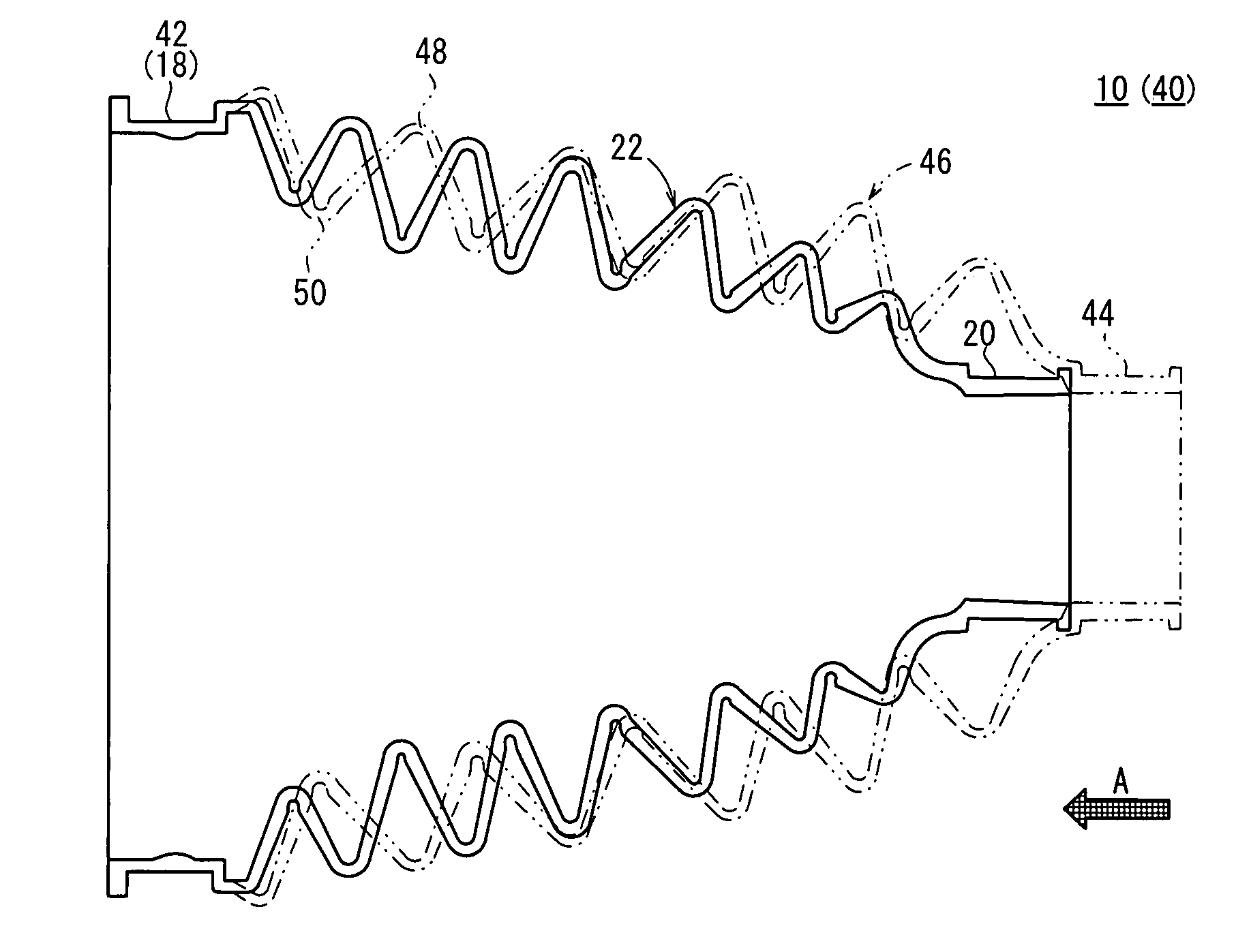
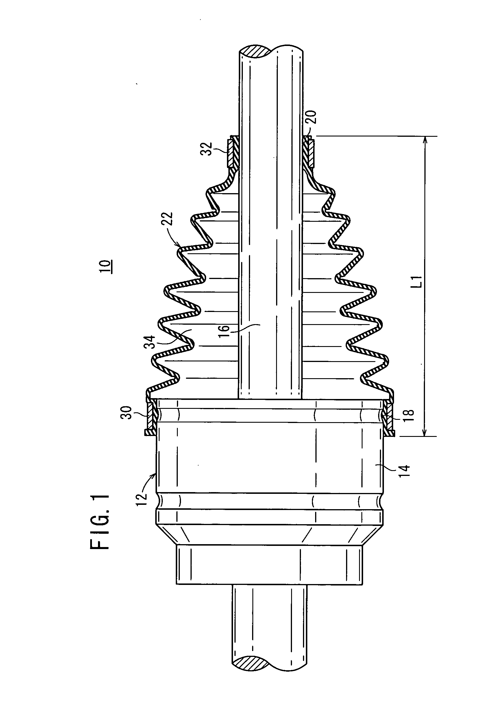
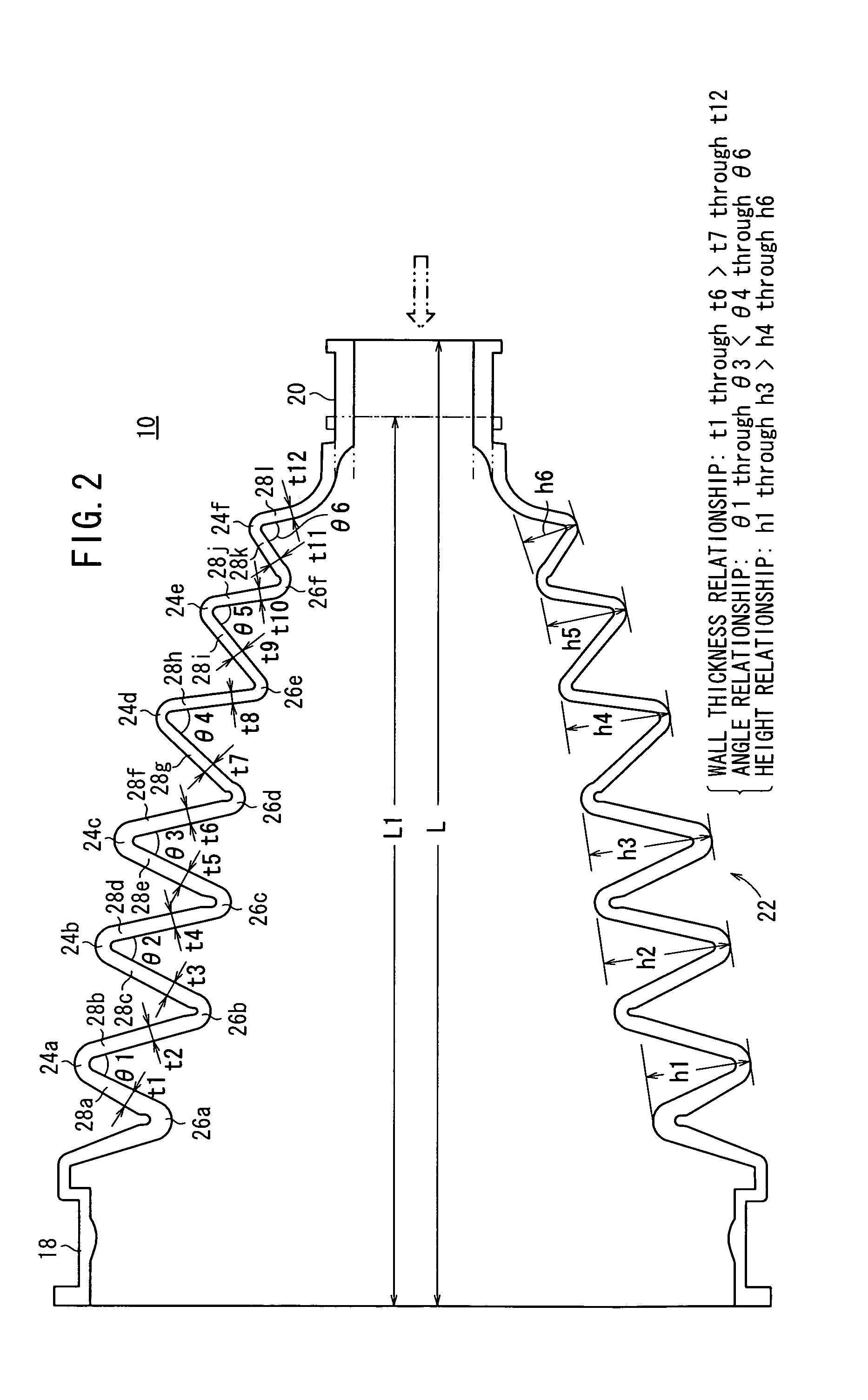
[0022]FIG. 1 shows in longitudinal cross section a universal joint boot 10 according to an embodiment of the present invention. The universal joint boot 10 is mounted on a universal joint, e.g., a constant velocity universal joint 12. FIG. 2 shows in enlarged longitudinal cross section the universal joint boot 10 before it is mounted on the constant velocity universal joint 12, i.e., when no external forces are applied to the universal joint boot 10.

[0023]As shown in FIG. 1, the constant velocity universal joint 12 comprises an outer member 14, which serves as an outer ring, and a shaft 16 tiltably coupled to the outer member 14. The universal joint boot 10 is made of rubber or synthetic resin, and comprises a large-diameter tubular member 18 into which the outer member 14 is inserted, a small-diameter tubular member 20 into which the shaft 16 is inserted, and a bellows member 22 interconnecting the large-diameter tubular member 18 and the small-diameter tubular member 20. The bello...


PUM


Abstract

A boot has a large diameter tube section, a small diameter tube section, and a bellows section for connecting the large diameter tube section and the small diameter tube section. The bellows section has, in a continuous manner, first to sixth crest sections and first to sixth root sections. The angles of opening of the inner peripheral surfaces of the crests of the first to third crest sections are set smaller than the angles of opening of the inner peripheral surfaces of the crests of the fourth to sixth crest sections. Further, the wall thicknesses of tilt sections are set smaller than the wall thickness of tilt sections.

Description

TECHNICAL FIELD[0001]The present invention relates to a universal joint boot comprising a large-diameter member into which an outer member of a universal joint is inserted, a small-diameter member into which a shaft of the universal joint is inserted, and a bellows member interconnecting the large-diameter member and the small-diameter member, wherein the bellows member becomes progressively smaller in diameter from the large-diameter member toward the small-diameter member.BACKGROUND ART[0002]Constant velocity universal joints for use on vehicles such as automobiles are known as universal joints. A typical universal joint includes a flexible boot made of rubber or synthetic resin. The boot comprises a large-diameter member into which an outer member (outer ring) of the universal joint is fixedly inserted, a small-diameter member into which a shaft of the universal joint is fixedly inserted, and a bellows member interconnecting the large-diameter member and the small-diameter member...

Claims


Application Information

Patent Timeline
Patent Type & Authority Applications(United States)
IPC IPC(8): F16D3/84
CPCF16D3/845F16J3/043F16J3/041
Inventor OKUBO, SHIGERU
Owner HONDA MOTOR CO LTD
Why Eureka
Try Eureka