Direct oxidation fuel cell system

a fuel cell and direct oxidation technology, applied in the direction of fuel cells, electrochemical generators, electrical equipment, etc., can solve the problems of low power generation, low power generation, dry surface of electrolyte membranes, etc., and achieve the effect of low cost, easy size reduction, and system size reduction

Inactive Publication Date: 2013-12-19
PANASONIC INTELLECTUAL PROPERTY MANAGEMENT CO LTD
View PDF2 Cites 3 Cited by
  • Summary
  • Abstract
  • Description
  • Claims
  • Application Information

AI Technical Summary

Benefits of technology

[0072]According to the present invention, the target supply flow rate is set in accordance with the load current detected by the load current sensor; and therefore, even if there is change in the load current, the oxidant gas could still be supplied to the fuel cell at an optimum flow rate which corresponds to that change.
[0073]Moreover, it would be possible to supply the oxidant gas to the fuel cell, always at an optimum flow rate, by using only the pressure sensor, i.e., without having to install a flow rate sensor for detecting the supply flow rate of the oxidant gas being supplied to the fuel cell, or a control valve, etc. for adjusting the foregoing supply flow rate.
[0074]Therefore, a fuel cell system can be produced at low cost, and easily be reduced in size.
[0075]Moreover, the system can easily be reduced in size, by using the positive displacement pump, e.g., the diaphragm pump, as the device for supplying the oxidant gas. Still moreover, since the oxidant gas flow conditioning unit enables reduction in the pressure pulsation caused by reciprocal motion of the diagphram valve, the power generated by the fuel cell can be made stable.

Problems solved by technology

If the amount of the air supplied is too small, water would accumulate on the surface of the electrolyte membrane; and the power generated would be very low.
On the contrary, if the amount of the air supplied is too large, the surface of the electrolyte membrane would become dry; and in this case also, the power generated would be very low.
When the amount of the air supplied is not appropriate, there would be a loss of balance in water reuse, i.e., in water balance; and the fuel cell would be unable to generate power for long hours.

Method used


Image

  • Direct oxidation fuel cell system
  • Direct oxidation fuel cell system
  • Direct oxidation fuel cell system

Examples


Embodiment Construction

[0085]In the following, an embodiment of the invention will be described with reference to drawings.

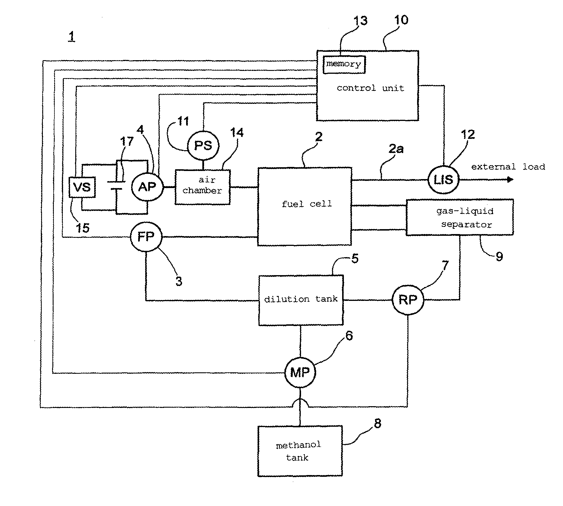
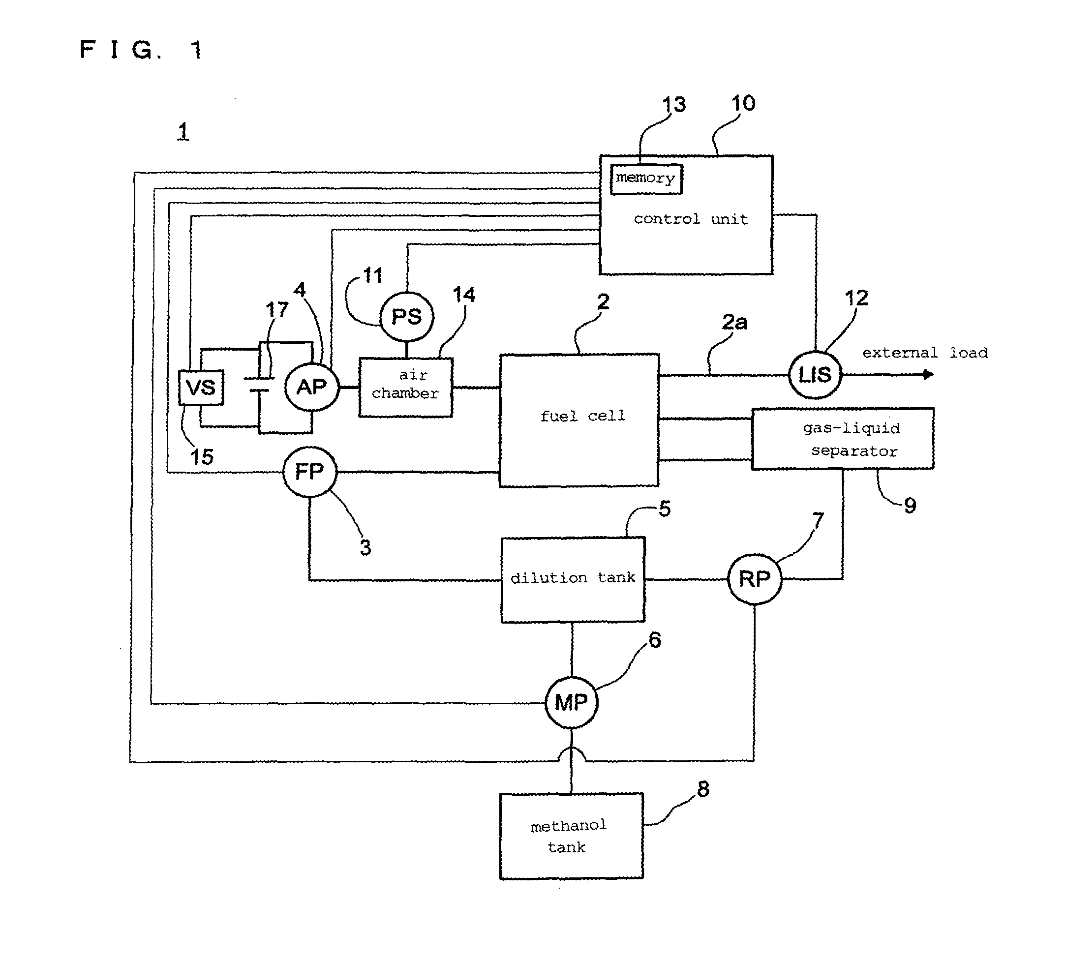
[0086]A fuel cell system 1 of FIG. 1 is a power supply system that uses a fuel cell 2 as the power supply source. Here, the fuel cell 2 also applies to a fuel cell stack comprising two or more of unit fuel cells (not shown) configured to generate power from a fuel and an oxidant gas. The fuel cell system 1 comprises: a fuel pump 3 for supplying the fuel to the fuel cell 2; an air pump 4 for supplying air, i.e., the oxidant gas, to the fuel cell 2; and an air chamber 14, i.e., an oxidant gas flow conditioning unit for inhibiting pulsation of a discharge pressure of the air pump 4; and a pressure sensor 11 for detecting the discharge pressure of the air pump 4. The air chamber 14 functions as a buffer chamber for inhibiting pulsation of the discharge pressure of the air pump 4, by temporarily storing the air sent from the air pump 4.

[0087]The air pump 4 can be a positive displacement pu...


PUM

PropertyMeasurementUnit
poweraaaaaaaaaa
drive voltageaaaaaaaaaa
discharge pressureaaaaaaaaaa

Abstract

A direct oxidation fuel cell system including: a fuel cell which generates power from fuel and oxidant gas; a positive displacement pump for supplying the oxidant gas; a power supply for applying drive voltage to the pump; an oxidant gas flow conditioning unit for inhibiting pulsation of discharge pressure of the pump; a pressure sensor for detecting the discharge pressure; a load current sensor for detecting load current of the cell; a voltage sensor for detecting the drive voltage; a first memory for storing first information on a target supply flow rate of the oxidant gas, set based on the load current; a second memory for storing second information on relation of the drive voltage, discharge pressure, and target supply flow rate; and a controller for controlling flow rate of the oxidant gas, by using the informations, and values from the pressure, load current, and voltage sensors.

Description

TECHINCAL FIELD[0001]The present invention relates to a direct oxidation fuel cell system, and more specifically, to a control system configured to control the amount of oxidant gas supplied to a fuel cell.BACKGROUND ART[0002]Fuel cells are becoming commercially available as the power source for automobiles, home cogeneration systems, etc. Recently, studies are also being conducted on use of fuel cells as the power source for small mobile electronic devices such as laptop computers, cellular phones, and personal digital assistants (PDAs). Furthermore, studies are also being conducted on use of fuel cells as the power source for outdoor recreation and emergency backup power. Particularly, since fuel cells can generate power continuously by being refueled, they are expected to be used as the power source for small mobile electronic devices and as portable power sources, and to thereby further improve the convenience thereof.[0003]Among fuel cells, direct oxidation fuel cells (DOFCs) g...

Claims


Application Information

Patent Timeline
Patent Type & Authority Applications(United States)
IPC IPC(8): H01M8/04
CPCH01M8/04104H01M8/1011H01M8/04395H01M8/04425H01M8/04567H01M8/04574H01M8/04753H01M8/04776Y02E60/50
Inventor MITSUI, MASAKI
Owner PANASONIC INTELLECTUAL PROPERTY MANAGEMENT CO LTD
Why Eureka
Try Eureka