Turbofan engine

Inactive Publication Date: 2010-07-01
UNITED TECH CORP
View PDF18 Cites 64 Cited by
  • Summary
  • Abstract
  • Description
  • Claims
  • Application Information

AI Technical Summary

Benefits of technology

[0006]A turbofan engine is provided that includes a fan nacelle surrounding a core nacelle. The core nacelle houses a spool. The fan and core nacelles provide a bypass flow path having a nozzle exit area. A turbofan is arranged within the fan nacelle upstream from the core

Problems solved by technology

Direct drive turbofan engines have several design chal

Method used


Image

  • Turbofan engine
  • Turbofan engine
  • Turbofan engine

Examples


Embodiment Construction

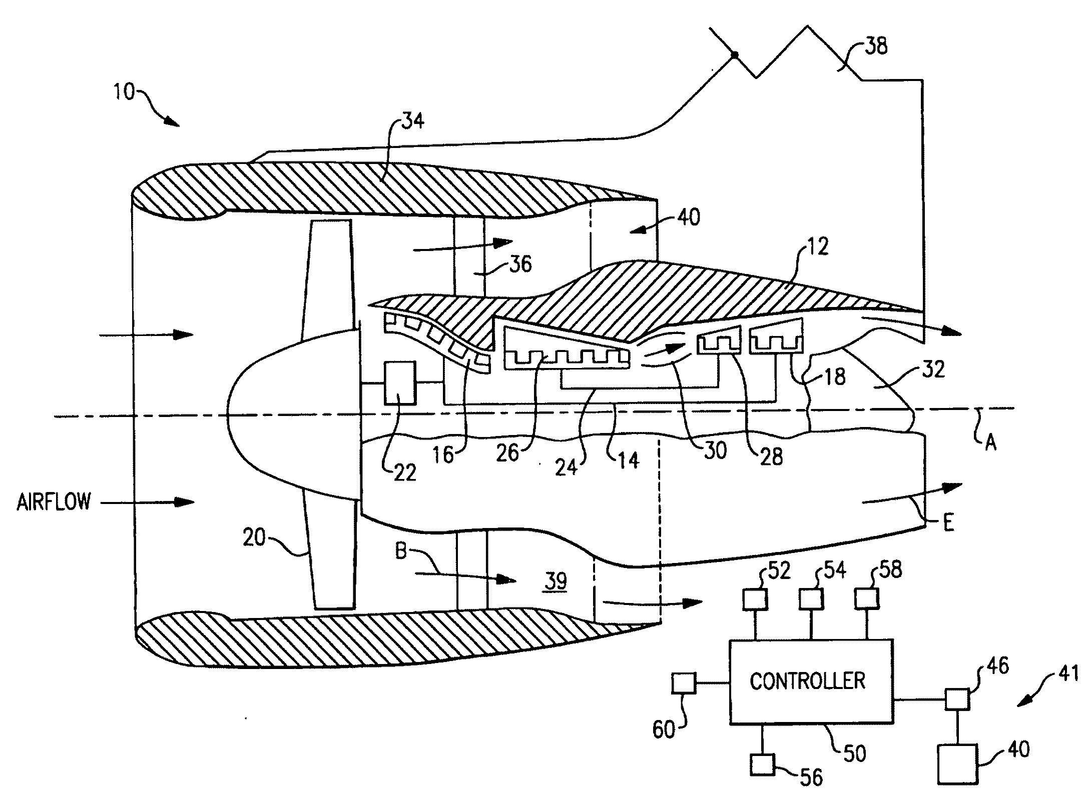
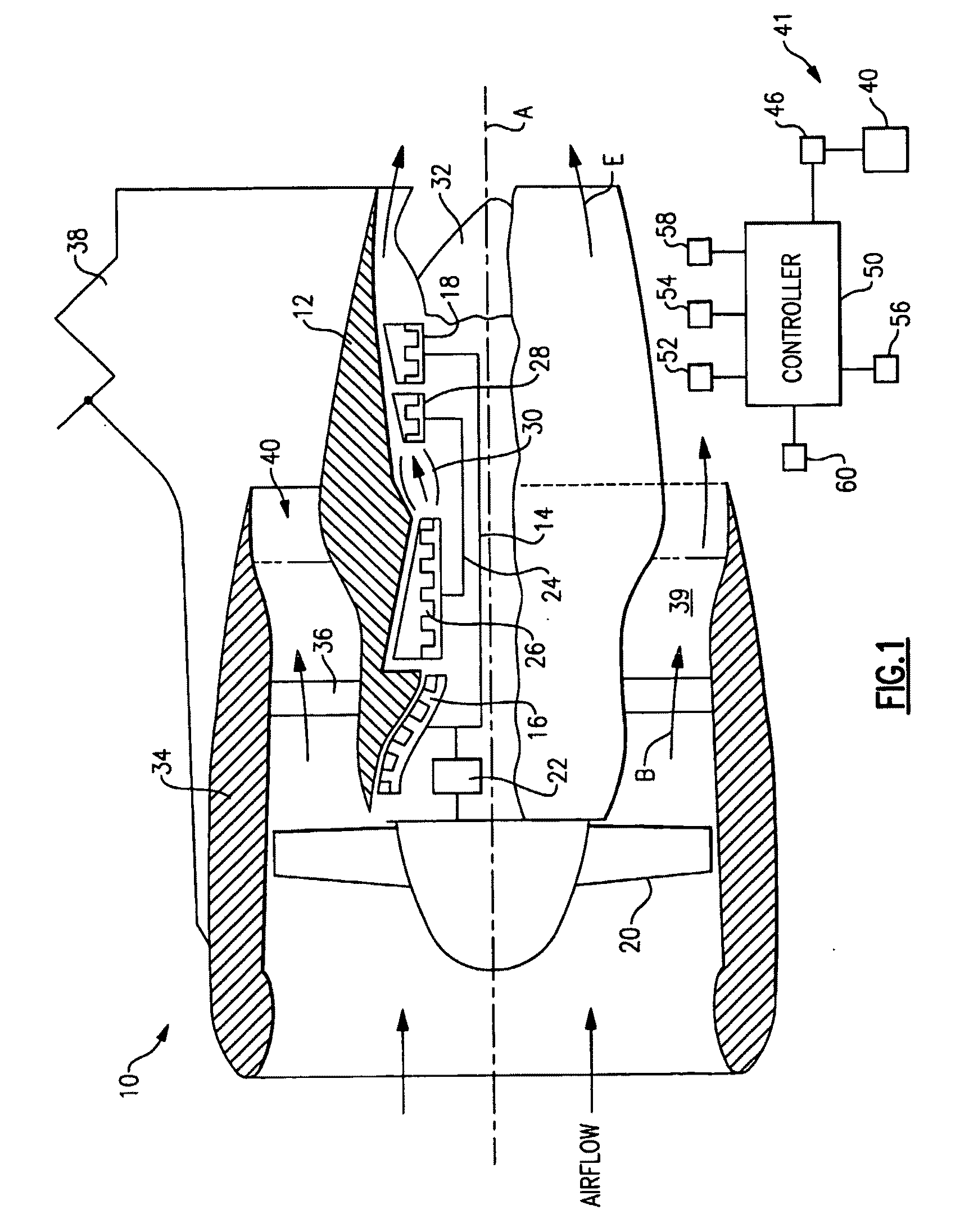
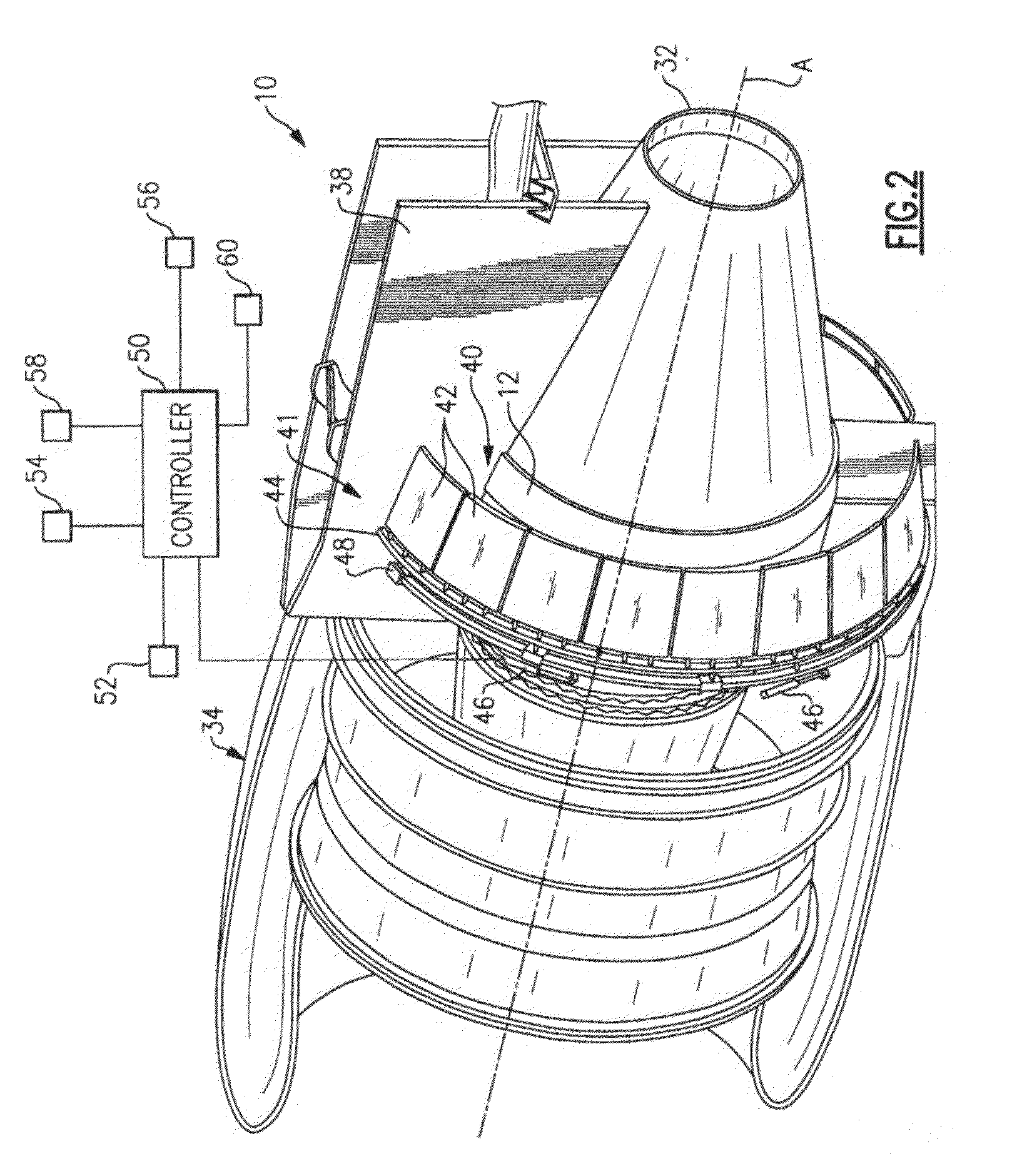
[0011]A geared turbofan engine 10 is shown in FIG. 1. A pylon 38 secures the engine 10 to an aircraft. The engine 10 includes a core nacelle 12 that houses a low spool 14 and high spool 24 rotatable about an axis A. The low spool 14 supports a low pressure compressor 16 and low pressure turbine 18. In the example, the low spool 14 drives a turbofan 20 through a gear train 22. The high spool 24 supports a high pressure compressor 26 and high pressure turbine 28. A combustor 30 is arranged between the high pressure compressor 26 and high pressure turbine 28. Compressed air from compressors 16, 26 mixes with fuel from the combustor 30 and is expanded in turbines 18, 28.

[0012]Airflow enters a fan nacelle 34, which surrounds the core nacelle 12 and turbofan 20. The turbofan 20 directs air into the core nacelle 12, which is used to drive the turbines 18, 28, as is known in the art. Turbine exhaust E exits the core nacelle 12 once it has been expanded in the turbines 18, 28, in a passage p...


PUM


Abstract

A turbofan engine is provided that includes a fan nacelle surrounding a core nacelle. The core nacelle houses a spool. The fan and core nacelles provide a bypass flow path having a nozzle exit area. A turbofan is arranged within the fan nacelle upstream from the core nacelle. A flow control device is adapted to effectively change the nozzle exit area to obtain a desired operating condition for the turbofan engine. A gear train couples the spool and turbofan for reducing a turbofan rotational speed relative to a spool rotational speed. A controller is programmed to respond to at least one sensor. The controller is programmed to effectively control the nozzle area.

Description

BACKGROUND OF THE INVENTION[0001]This invention relates to a turbofan engine, and more particularly, the invention relates to a turbofan engine having an effectively variable nozzle exit area.[0002]A turbofan engine typically includes a fan nacelle surrounding a core nacelle. A spool is housed in the core nacelle and supports a compressor and turbine. A turbofan is arranged in the fan nacelle upstream from the core nacelle. Flow from the turbofan bypasses the core nacelle through a bypass flow path arranged between the core and fan nacelles. The bypass flow path includes an exit nozzle that is typically fixed. In many turbofan engines, the turbofan is driven directly by the spool and rotates at the same speed as the spool.[0003]The engine's design is affected by such factors as the pressure ratio of the turbofan. Propulsive efficiency improvements, and hence fuel consumption, can be gained by reducing the turbofan pressure ratio. Direct drive turbofan engines have several design cha...

Claims


Application Information

Patent Timeline
IPC IPC(8): F02K3/06F02K1/06F02C7/36
CPCF02C7/36F02K1/1207F02K3/06F05D2220/36F05D2260/40311
Inventor GRABOWSKI, ZBIGNIEW M.MCVEY, WILLIAM J.
Owner UNITED TECH CORP
Why Eureka
Try Eureka