
System and Method for Tactile Currency Identification

a currency and tactile technology, applied in the field of systems, can solve the problems of difficulty in the difficulty of identifying the denomination of the currency, and the difficulty of identifying the currency denomination, etc., and achieve the effect of convenient identification

Inactive Publication Date: 2010-07-01
FRACEK GEORGE
View PDF8 Cites 11 Cited by
  • Summary
  • Abstract
  • Description
  • Claims
  • Application Information

AI Technical Summary

Benefits of technology

The present system and method for tactile currency identification creates or modifies faux or legal tender bills so that they can be easily identified by touch. This is useful for visually impaired users or in low light conditions. The system involves strategically positioning tactile indicators along the periphery of the bill, including an orientation indicator and a denomination indicator. The orientation indicator helps orient the bill to the user, while the denomination indicator identifies the value of the bill. The bill may also have a warning indicator to alert the user that it is faux currency. The system does not require any change in the size or shape of the bill and is cost-effective and simple-yet-elegant.

Problems solved by technology

The lack of tactile distinctiveness between various denominations of these bills poses a significant problem for the blind, and the visually impaired.
However, these existing designs do not utilize the relative positioning of various inserts, Braille elements, perforations, and / or raised elements to promote identification of the denomination of the currency.
In addition, the level of tactile feel provided by these designs may be problematic to the blind and / or visually impaired who also have limited sensation in their extremities, which is a common problem among diabetics.

Method used


Image

  • System and Method for Tactile Currency Identification
  • System and Method for Tactile Currency Identification
  • System and Method for Tactile Currency Identification

Examples


Embodiment Construction

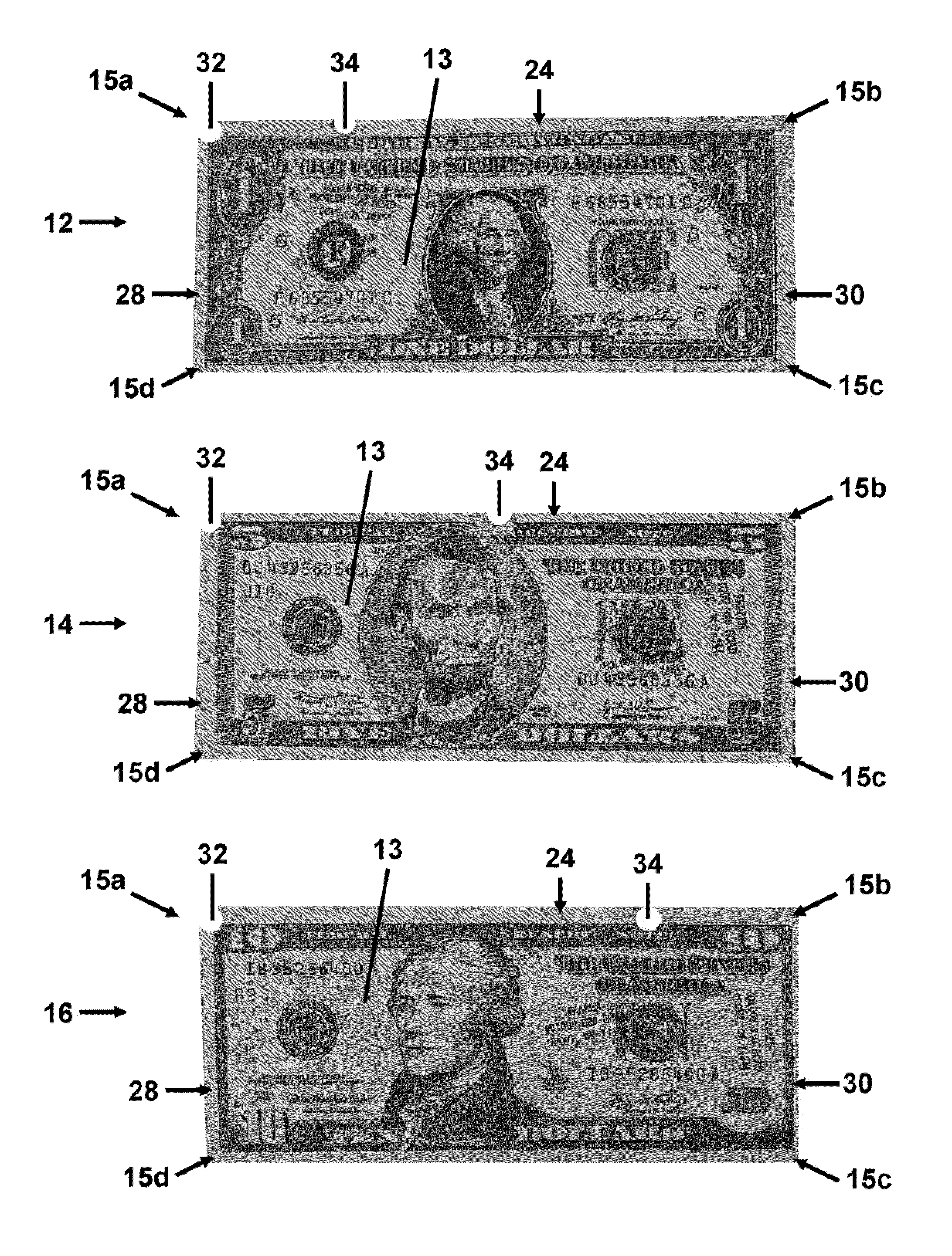
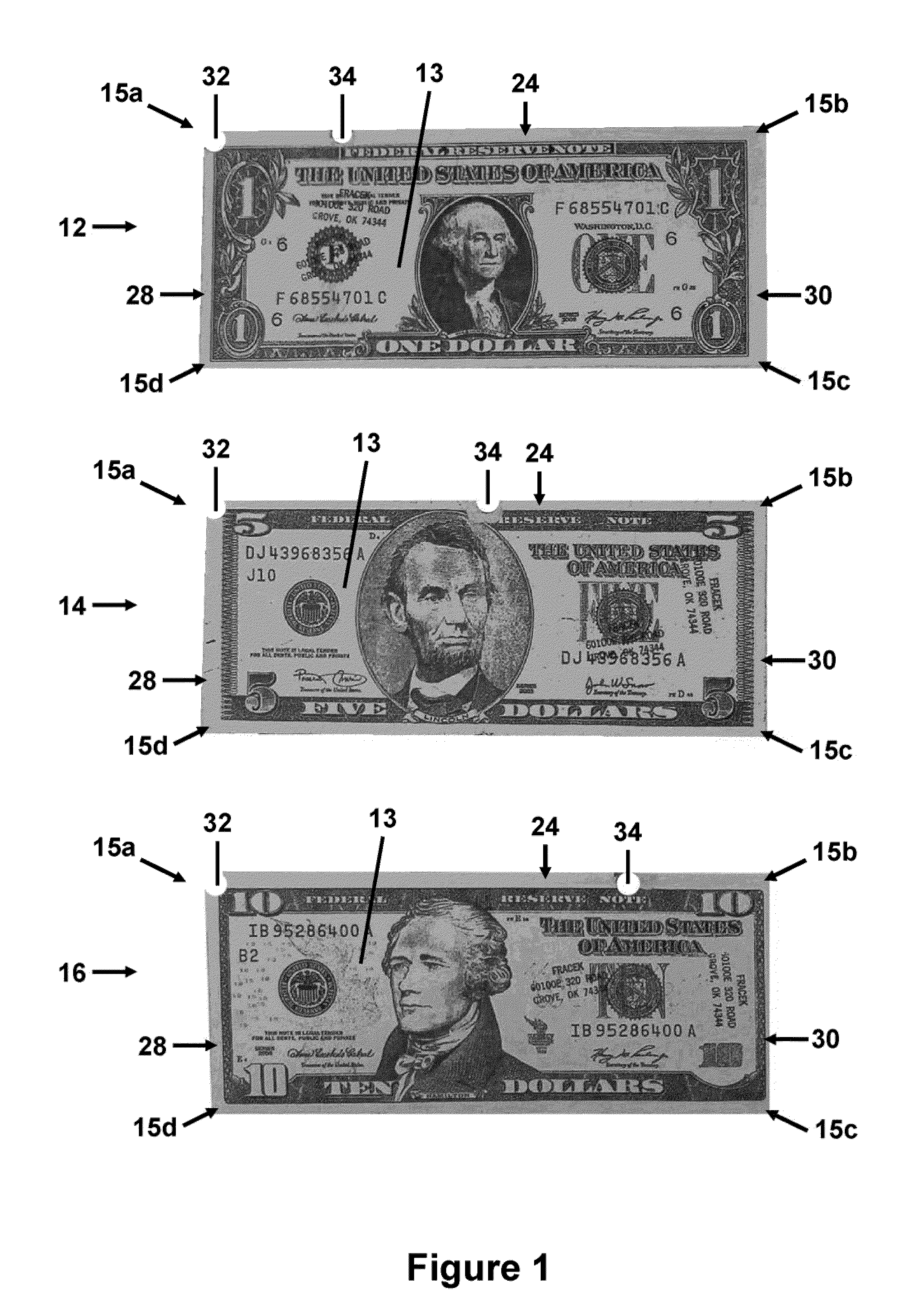
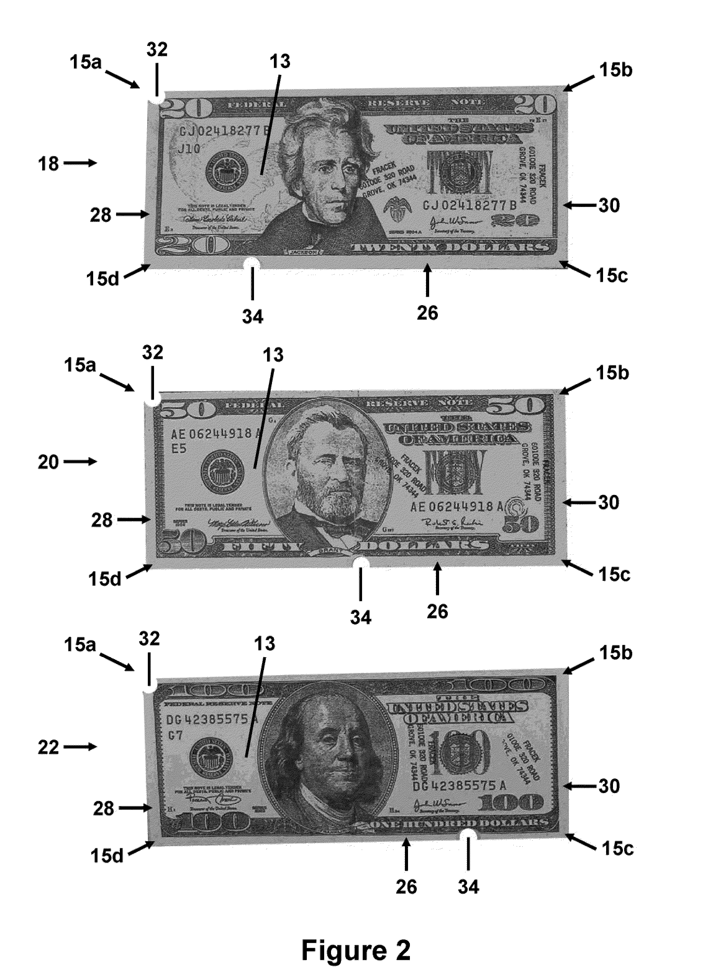
[0022]The present system and method for tactile currency identification may be used to create or modify a bill by positioning tactile indicators along the periphery of the bill for tactile orientation of the bill to the user, and tactile identification of the bill's denomination. The presently preferred embodiment of the system and method relating to bills issued by the United States Treasury is illustrated in FIGS. 1-3. Each of the bills in these figures has a front surface 13 on one side of the bill and a rear surface on the opposite side (not shown), and four corners 15a, 15b, 15c, and 15d.

[0023]Turning now to FIG. 1, bills issued by the United States Treasury are depicted in denominations of one dollar 12, five dollars 14 and ten dollars 16. In this embodiment, a semi-circular orientation notch 32 is positioned in the upper left hand corner 15a of each bill when the front surface 13 is facing up and orientated right-side up. There are no notches in any of the remaining three co...


PUM

PropertyMeasurementUnit
shapeaaaaaaaaaa
sizeaaaaaaaaaa
sizesaaaaaaaaaa

Abstract

A tactile orientation indicator is positioned along the periphery of a bill, and a tactile denomination indicator is positioned elsewhere along the periphery of the bill. The user of the bill may then use their tactile senses to feel along the edges of the bill to orient the bill to a pre-determined orientation based on the location of the orientation indicator. The user then feels along the periphery of the bill to locate the denomination indicator. Using a predetermined system associating the location of the denomination indicator with a particular bill denomination, the user may then identify the denomination of the bill even if blind or otherwise visually impaired.

Description

RELATED APPLICATIONS[0001]This application makes reference to, claims priority to, and claims the benefit of United States Provisional Patent Application Ser. No. 61 / 141,488, entitled “System and Method for Tactile Currency Identification,” filed Dec. 30, 2008, the complete subject matter of which is hereby incorporated herein by reference in its entirety.FEDERALLY SPONSORED RESEARCH OR DEVELOPMENT[0002][Not Applicable]MICROFICHE / COPYRIGHT REFERENCE [0003][Not Applicable]BACKGROUND OF THE INVENTION[0004]The present system and method for tactile currency identification generally relates to the identification of physical items by tactile feel. More specifically, the present system and method for tactile currency identification relates to a system and method for the identification of bills by denomination using strategically positioned tactile indicators.[0005]The bills printed by the Treasury Department of the United States of America have been changed in several respects over the las...

Claims


Application Information

Patent Timeline
Patent Type & Authority Applications(United States)
IPC IPC(8): B42D15/00B23P17/04
CPCB42D25/29Y10T29/49826
Inventor FRACEK, GEORGE
Owner FRACEK GEORGE
Learn More