Impact absorbing member for vehicle

a technology for impact absorbing components and vehicles, which is applied to vehicle components, rubber dampers, bumpers, etc., can solve the problems of affecting the mountability of the vehicle, the inability to obtain the desired impact-energy absorbing performance of the crash box b>14/b>r, etc., and achieves excellent impact absorbing performance. , the effect of increasing the mountability of the impact absorbing member on the vehicl

Inactive Publication Date: 2010-07-01
TOYODA IRON WORKS CO LTD
View PDF10 Cites 40 Cited by
  • Summary
  • Abstract
  • Description
  • Claims
  • Application Information

AI Technical Summary

Benefits of technology

[0014]The present invention was accomplished considering the above situations, and has an object to provide an impact absorbing member for a vehicle which occupies the less mounting space in the vehicle as well as is prevented from falling laterally even upon application of the impact load in an oblique direction of the vehicle, so as have an excellent impact absorbing performance stably.
[0023]Accordingly, when the impact absorbing member is disposed such that the pair of reinforcing side walls are located at the both end areas in the vehicle upper-lower direction, and the reinforcing side walls and the flanges are substantially parallel (parallel or approximately parallel) to the vehicle width direction as in the fifth invention, even if the impact load applied in the oblique direction of the vehicle generates the moment load in the impact absorbing member, owing to disposition of the flanges the impact absorbing member is effectively suppressed from falling laterally, i.e., lateral falling, so that the excellent impact absorbing performance of the impact absorbing member can be stably obtained. In such a case, because the both lateral portions of each of the flanges are formed substantially parallel (parallel or approximately parallel) to the reinforcing side wall, the impact absorbing member can be compactified or miniaturized, compared with a case where flanges are provided so as to project radially outward, as well as it is suppressed from the lateral falling appropriately due to the impact load acting in the oblique direction of the vehicle. Accordingly, the mountability of the impact absorbing member on the vehicle can be increased.
[0025]According to the third aspect of the present invention, the width dimension between the both ends of each of the flanges in the section perpendicular to the axial direction of the tubular body portion, is equal to or less than the width dimension between the outer surfaces of the tubular body portion in the direction parallel to the reinforcing side wall. Therefore, the width dimension of the impact absorbing member including the pair of flanges, that is, the dimension of the impact absorbing member in the vehicle width direction when the impact absorbing member is disposed as in the fifth aspect, can be maintained at the same magnitude as that of the conventional products. As a result, without impairing mountability on the vehicle, the impact absorbing member can be improved to be appropriately suppressed from the lateral falling due to the impact load acting in the oblique direction of the vehicle, and the impact absorbing performance thereof can be improved.
[0026]According to the fourth aspect of the present invention, each of the flanges is formed integrally with the tubular body portion so that the central portion thereof is shared with the reinforcing side wall. Therefore, the plate thickness of the reinforcing side wall of the tubular body portion can be selected or decided to be equal to that of other side walls, so that a decrease in the impact absorbing performance resulting from a local increase in the plate thickness can be suppressed. Moreover, the thickness of a part of reinforcing side wall where the central portion of the flange is connected, and the thickness of the both lateral portions of the flange branching off the reinforcing side wall to spread outward therefrom, can be selected or decided to be equal to the thickness of other side walls of the tubular body portion so as to maintain an excellent moldability when the tubular body portion and the flanges are molded or formed integrally by extrusion moldings or the like.
[0027]In the fifth aspect of the present invention, the impact absorbing member is disposed in the posture such that a pair of reinforcing side walls are located at the both end areas in the vehicle upper-lower direction, and the reinforcing side walls and the flanges are substantially parallel to the vehicle width direction. According to such arrangement, even when the impact load applied to the vehicle in the oblique direction thereof generates the moment load, the impact absorbing member is suppressed from lateral falling owing to disposition of the flanges, and can render the excellent impact absorbing performance stably.BEST MODE FOR CARRYING OUT THE INVENTION

Problems solved by technology

As a result, desired impact-energy absorbing performance of the crash box 14R may not be obtained.
However, due to disposition of the flanges projecting radially outward, the impact absorbing member occupies a large space in the vehicle to impair mountability thereof on the vehicle.

Method used


Image

  • Impact absorbing member for vehicle
  • Impact absorbing member for vehicle
  • Impact absorbing member for vehicle

Examples


embodiment

PREFERRED EMBODIMENT

[0048]Hereafter, preferred embodiments of the present invention will be described in detail with reference to the drawings.

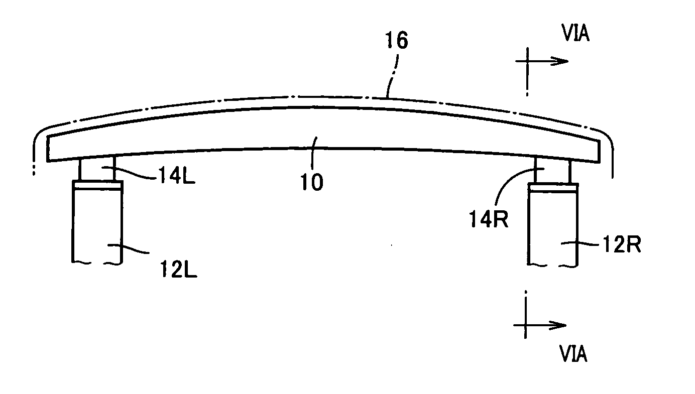
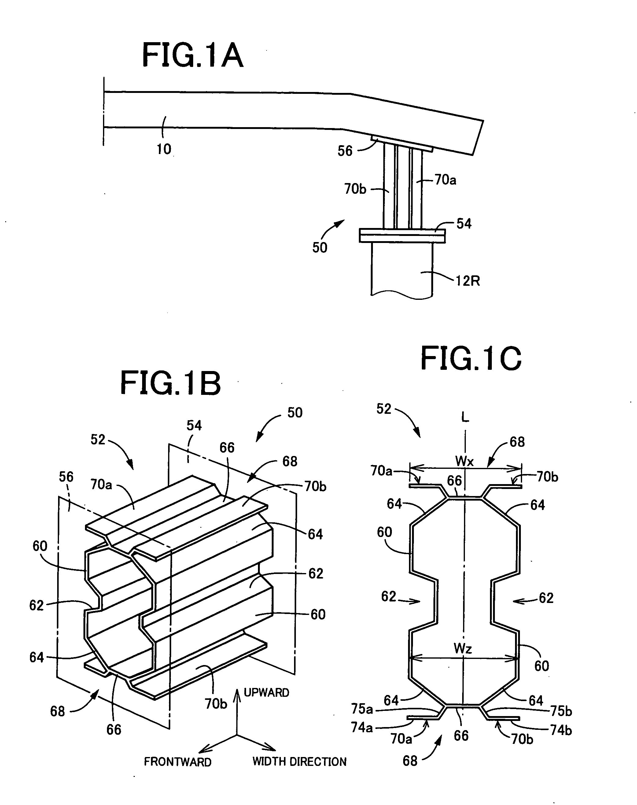
[0049]A crash box 50 in FIGS. 1A to 1C is disposed between the side member 12R and the bumper beam 10 to be used in place of the crash box 14R in FIGS. 6A to 6C, and corresponds to an impact absorbing member for a vehicle of the present invention. In FIG. 1A which is a plan view showing the right half of the vehicle, a left half is symmetrically constituted with the right half about a center line. The crash box 50 comprises a main body portion 52 having a tubular shape with a closed section of a flat octagon which is elongated in one direction as a basic sectional shape, and a pair of mounting plates 54 and 56 integrally weld-fixed to the both axial ends of the main body portion 52, respectively. The main body portion 52 corresponds to a tubular body portion of the present invention.

[0050]The crash box 50 is disposed between the side member 1...


PUM


Abstract

Flanges (68) are provided on outer sides (in an upper-lower direction) of a pair of narrow side walls (66) of a crash box (50). Each of flanges (68) is provided to be connected to the narrow side wall (66) at the central portion thereof, and the both lateral portions thereof (wing-like flanges (70a, 70b)) extend parallel to the narrow side walls (66) and in the opposite directions relative to each other. Therefore, even when an impact load is applied to the crash box (50) in an oblique direction of the vehicle, owing to disposition of the flanges (68) the crush box (50) is suppressed from lateral falling, so that excellent impact-absorbing property is stably obtained. Because the flanges (68) are formed parallel to the narrow side walls (66), the impact absorbing member can be appropriately prevented from the lateral falling resulted from the impact load acting in an oblique direction of the vehicle, and can be compactified in size. As a result, mountability on a vehicle is improved.

Description

[0001]This application is based on Japanese Application No. 2008-331911 filed on Dec. 26, 2008, and content there of is incorporated therein for reference.BACKGROUND OF THE INVENTION[0002]1. Field of the Invention[0003]The present invention relates to an impact absorbing member for a vehicle. More specifically, the invention relates to the impact absorbing member which hardly falls laterally when it receives an impact load from a front or back of a vehicle obliquely, and which is prevented from impairment of impact absorbing performance.[0004]2. Description of the Related Art[0005]An impact absorbing member for a vehicle is mounted to a frond end portion or the like of a vehicle to absorb an impact load applied to the vehicle. One example thereof is an impact absorbing member having a tubular body portion with a closed section formed of a plurality of plate-like side walls. Some of the plurality of side walls are formed a concave groove(s) which is recessed inwardly of the tubular b...

Claims


Application Information

Patent Timeline
Patent Type & Authority Applications(United States)
IPC IPC(8): B60R19/02
CPCB60R19/34F16F7/12
Inventor NAKANISHI, MAKOTOKANO, MITSUTOSHI
Owner TOYODA IRON WORKS CO LTD
Why Eureka
Try Eureka