Self-sensing dielectric actuator system

Inactive Publication Date: 2010-07-01
BOARD OF RGT NEVADA SYST OF HIGHER EDUCATION ON BEHALF OF THE UNIV OF NEVADA RENO
View PDF12 Cites 33 Cited by
  • Summary
  • Abstract
  • Description
  • Claims
  • Application Information

AI Technical Summary

Problems solved by technology

The more actuators and sensors, the bulkier and more cumbersome the system becomes.
This problem becomes particularly acute in systems designed for micro- to meso-scale applications.
For example, robotic systems that mimic the motion of small animals such as insects, earthwor

Method used


Image

  • Self-sensing dielectric actuator system
  • Self-sensing dielectric actuator system
  • Self-sensing dielectric actuator system

Examples


Embodiment Construction

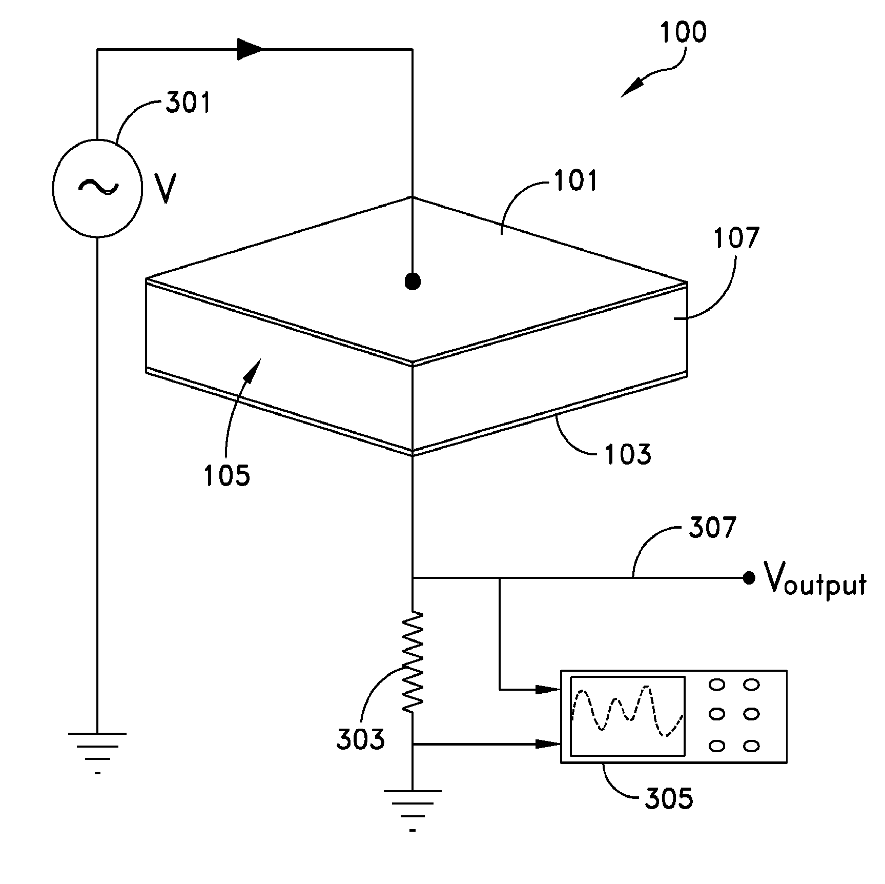
[0029]Several embodiments of a self-sensing actuator are described. Some embodiments use an electro-active polymer such as a dielectric elastomer (DE) for a dielectric. A self-sensing actuator according to the principles of the invention is simultaneously operable as an actuator and a sensor without additional independent sensing devices or additional electrodes.

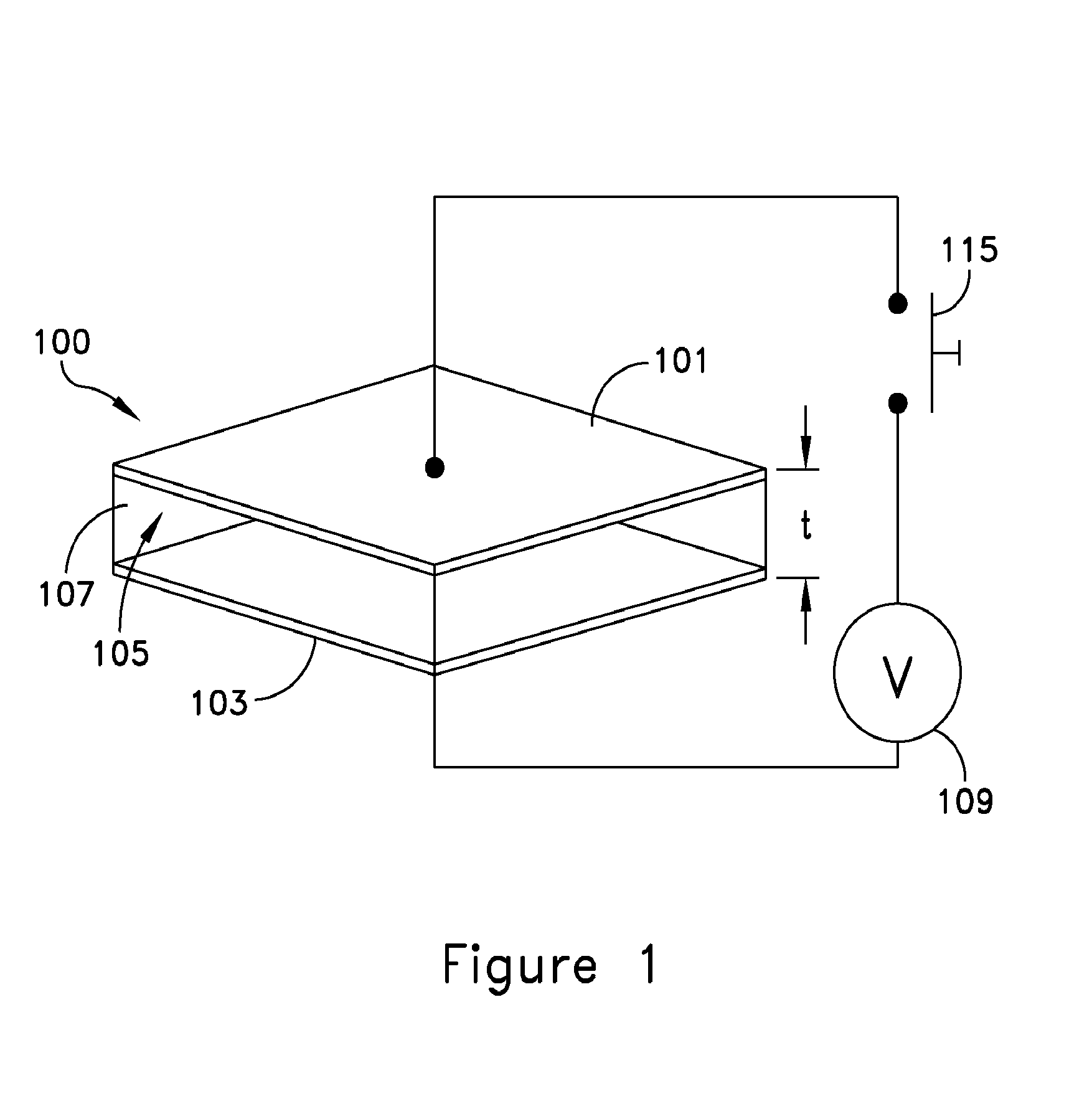
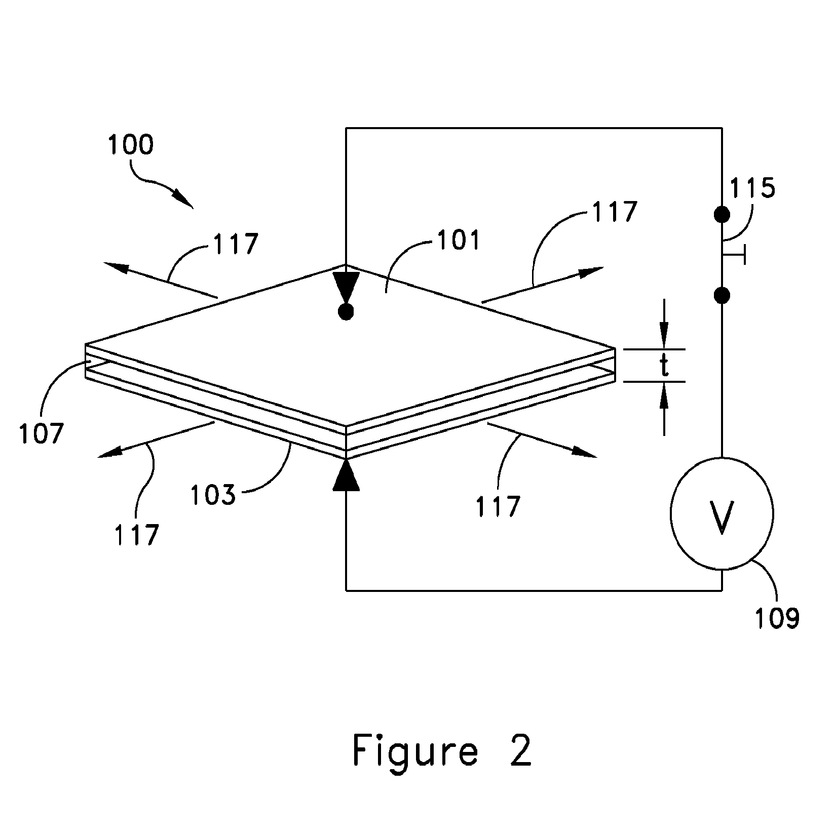
[0030]An embodiment of a self-sensing dielectric actuator system 100 is shown in FIGS. 1 and 2. A deformable first electrode 101 is separated from a second electrode 103 by a space 105. The second electrode may also be deformable. A dielectric material 107, for example a dielectric elastomer (DE), is disposed in the space 105 between the electrodes. The electrodes may be separate sheets of material or they may be formed on opposing surfaces of the dielectric material.

[0031]An actuating signal source 109 is configured to apply an electric potential across the electrodes and thereby cause the dielectric material to deform the ...


PUM


Abstract

A self-sensing dielectric actuator system. The system has a deformable dielectric material between two electrodes. A relatively low frequency actuating signal is applied to the electrodes and thereby causes the dielectric material to deform, moving at least one electrode. A relatively high frequency sensing signal applied across the electrodes indicates how far the electrode has moved. The system may be calibrated by using a laser or other sensor to mechanically measure the amount of movement. An object may be displaced a desired distance by coupling the object to the electrode and using the sensing signal to measure how far the object has moved.

Description

[0001]This patent application claims priority from U.S. Provisional Patent Application No. 60 / 961,801 filed 23 Jul. 2007, the entire content of which is incorporated herein by this reference.BACKGROUND [0002]Various actuators, such as electrical motors, pneumatic or hydraulic cylinders, and magnetic solenoids are commonly used in many types of engineering disciplines and applications. Typically, actuators are operable to displace one object relative to another object. The magnitude of the displacement of an actuator generally is an important factor in the operation of engineering systems, such as feedback control systems that use closed-loop control. In closed-loop control, the displacement of an actuator is typically measured by a sensor coupled to the actuator. Sensors can include instruments such as angular encoders and tachometers that can measure angular displacement, and linear displacement sensors such as linear encoders and variable differential transformers.[0003]Many compl...

Claims


Application Information

Patent Timeline
IPC IPC(8): H01L41/107
CPCH01G5/16H01L41/042H02N1/006H10N30/802
Inventor KIM, KWANG J.JUNG, KWANGMOK
Owner BOARD OF RGT NEVADA SYST OF HIGHER EDUCATION ON BEHALF OF THE UNIV OF NEVADA RENO
Why Eureka
Try Eureka