Apparatus and Process for Removal of Carbon Monoxide

a carbon monoxide and apparatus technology, applied in the direction of catalyst regeneration/reactivation, physical/chemical process catalysts, separation processes, etc., can solve the problems of reducing the selectivity of desired products, reducing capacity, and increasing coking, so as to reduce the level of carbon monoxide, reduce the cost of catalyst coking, and improve the effect of operability

Inactive Publication Date: 2010-07-01
UOP LLC
View PDF21 Cites 0 Cited by
  • Summary
  • Abstract
  • Description
  • Claims
  • Application Information

AI Technical Summary

Benefits of technology

[0008]The embodiments disclosed herein can provide a process and an apparatus for reducing the levels of carbon monoxide in a reducing gas, such as hydrogen. As a result, coking of the catalyst can be minimized in a reforming reaction zone and thereby can improve operability.DEFINITIONS

Problems solved by technology
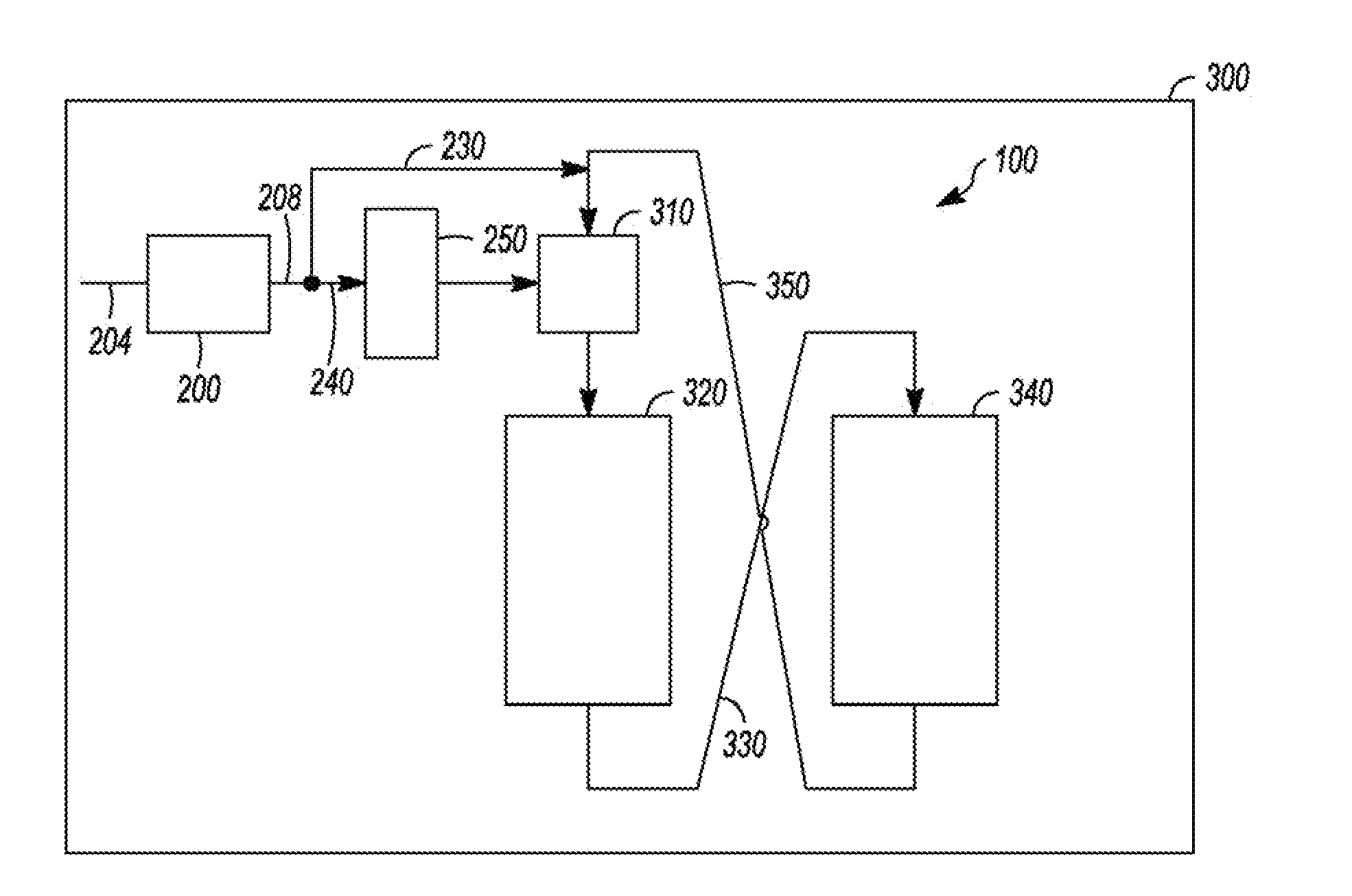
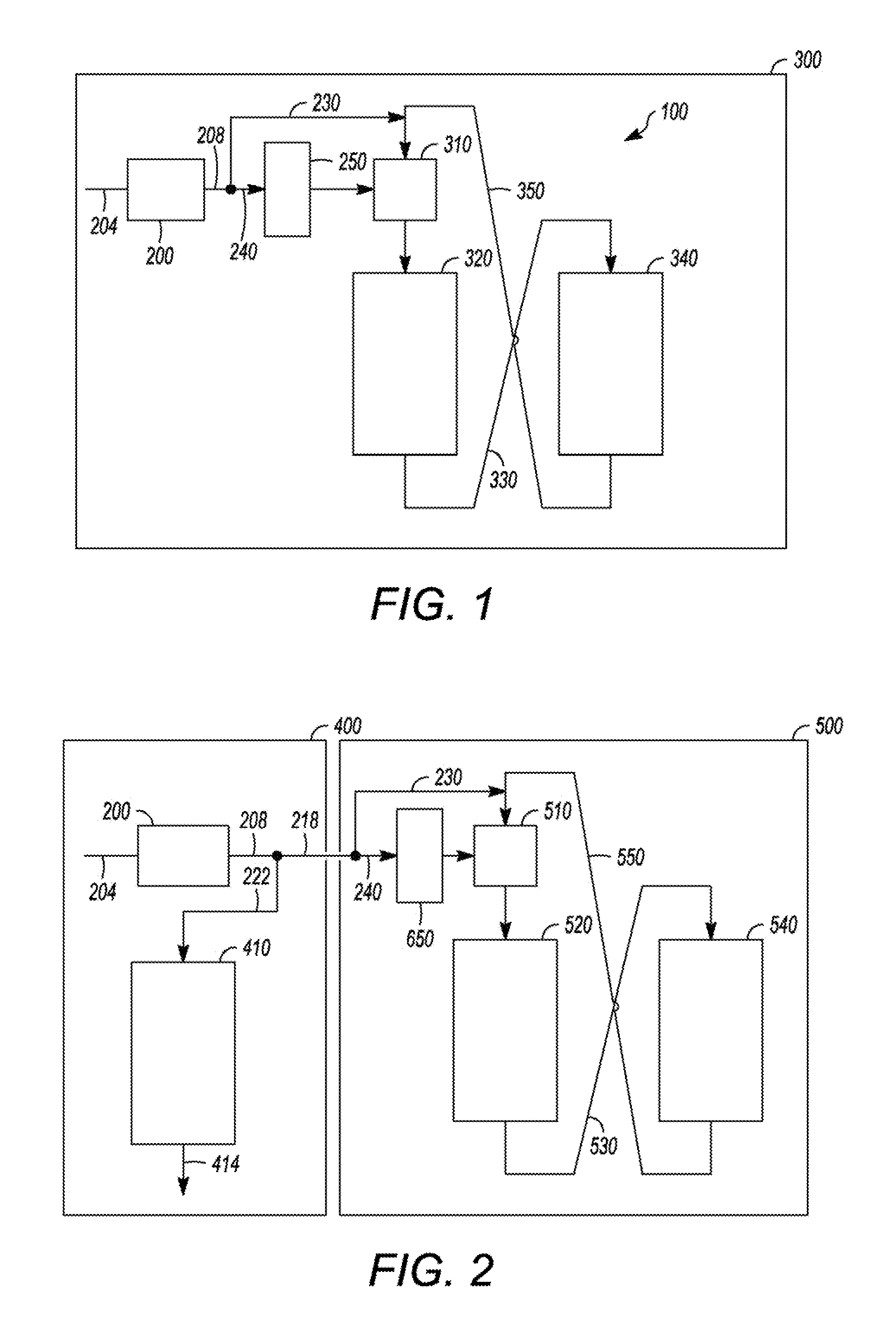
Increased coking can be detrimental by lowering catalytic activity and decreasing selectivity of desired products.
In addition, operating conditions may need to be changed resulting in reduced capacity.
As an example, the feed rate may need to be lowered in order to increase the hydrogen:hydrocarbon ratio to mitigate the coke formation, which in turn can result in product and profitability losses.

Method used


Image

  • Apparatus and Process for Removal of Carbon Monoxide
  • Apparatus and Process for Removal of Carbon Monoxide

Examples


example 1

[0030]Two catalysts are prepared with a spherical alumina support. The first catalyst has a final composition of 0.25%, by weight, platinum (Pt) and 0.30%, by weight, tin (Sn) (catalyst A) while a second catalyst has a final composition of 0.30%, by weight, Pt and 0.30%, by weight, Sn (catalyst B). Each catalyst is oxychlorinated to disperse the platinum and achieve a chloride level of about 0.9-about 1%, by weight, chloride (Cl) on the catalyst.

[0031]Each catalyst is then exposed to different reduction conditions in a reforming pilot plant using naphtha feed of 55.5% paraffins, 31.7% naphthenes, and 12.8% aromatics (all percents by weight) at a hydrogen:hydrocarbon mole ratio of 2, a liquid hourly space velocity (LHSV) of 1.7 hr−1, and a pressure of 620 kPa. Catalyst activity is determined by the temperature needed to maintain a target octane. Yields are calculated based on on-line gas and liquid effluent chromatography analysis. Runs are equal in length of time and spent catalyst ...

example 2

[0032]Similar experiments are conducted as in Example 1 using a commercially manufactured continuous catalyst regeneration catalyst (catalyst C) containing 0.25% Pt, 0.3% Sn, and 0.94% Cl (all percentages by weight). Catalyst C is split into two portions for reduction at temperatures of 399° C. and 566° C. in the presence of 0 vppm carbon monoxide. Results are depicted in Table 2.

TABLE 2Yield and Activity Results of 56 m3 of Naphtha Feed Per m3 of CatalystH2 Reduction ConditionsPilot Plant ResultsClTimeTemp.COC5+Activity Temp.Average CarbonCatalyst(wt. %)(hour)(° C.)(vppm)(wt. %)(° C.)(g / 100 cc)Delta %C0.902399086.25192.44BaseC0.782566086.35192.03−16.8%

[0033]Results indicate that higher reduction temperatures produce about 17% less coke for catalyst C. The C5+ yields and activity remain relatively constant.

example 3

[0034]Further experiments with catalyst A and B are conducted for up to 10 hours, in the presence of 0 vppm of carbon monoxide with samples analyzed at 2, 4 and 10 hours. The data at 4 hours is from Table 1. Results are depicted in Table 3.

TABLE 3Yield and Activity Results of 56 m3 of Naphtha Feed Per m3 of CatalystH2 Reduction ConditionsPilot Plant ResultsClTimeTemp.COC5+Activity Temp.Average CarbonCatalyst(wt. %)(hour)(° C.)(vppm)(wt. %)(° C.)(g / 100 cc)Delta %A0.9845651086.65171.74BaseA0.942565086.35161.42−18.4%A0.8710565086.15181.34−23.0%B0.9945651086.85182.15BaseB0.952565086.55171.77−17.7%B0.8710565086.85181.56−27.4%

[0035]As depicted, extended reduction time in substantially carbon monoxide free hydrogen gas results in further coke reduction ranging from about 23-about 27% reduction, as compared to the base condition of 4 hours, as depicted in Table 1.


PUM

PropertyMeasurementUnit
pressureaaaaaaaaaa
pressureaaaaaaaaaa
pressureaaaaaaaaaa

Abstract

One exemplary embodiment can be a process for lowering an amount of carbon monoxide in a stream rich in hydrogen. The process can include passing the stream rich in hydrogen through a carbon monoxide removal zone to produce a product stream having no more than about 10 vppm carbon monoxide and communicating the product stream to a reduction zone receiving a catalyst comprising unreduced metal species.

Description

CROSS REFERENCE TO RELATED APPLICATION[0001]This application is a Division of copending application Ser. No. 12 / 177,851 filed Jul. 22, 2008, the contents of which are hereby incorporated by reference in its entirety.FIELD OF THE INVENTION[0002]This invention generally relates to an apparatus and a process for reducing a catalyst typically used in a reforming process.DESCRIPTION OF THE RELATED ART[0003]During the reforming of a hydrocarbon stream, such as naphtha, often a continuous catalyst regeneration reforming unit is utilized. In such a unit, a reduction zone may be provided to reduce the catalyst before the catalyst can enter a reforming reactor. If carbon monoxide is present in the reduction zone, higher coke may form on the catalyst in the reforming reactor. Generally, such carbon monoxide originates from the hydrogen stream used to reduce the catalyst. Typically, the hydrogen stream can contain about 5-about 20 volume parts-per-million (hereinafter may be abbreviated “vppm”)...

Claims


Application Information

Patent Timeline
Patent Type & Authority Applications(United States)
IPC IPC(8): B01J19/00C01B32/40
CPCB01D53/02B01D53/864B01D2251/202B01D2253/108B01D2255/1026B01D2255/20746B01D2255/20753B01D2256/16B01D2256/24B01D2257/502B01J23/96B01J38/10C10G35/06
Inventor LAPINSKI, MARK P.ROSIN, RICHARD R.
Owner UOP LLC
Why Eureka
Try Eureka