Control Component and Method for an Energy Management Unit in an Industrial Automation Arrangement

a technology of energy management unit and control component, applied in the field of control systems, can solve the problems of high degree of complexity of control task, unsatisfactory control effect, and high energy consumption of individual automation components, and achieve the effect of simplifying energy managemen

Inactive Publication Date: 2010-07-01
SIEMENS AG
View PDF10 Cites 29 Cited by
  • Summary
  • Abstract
  • Description
  • Claims
  • Application Information

AI Technical Summary

Benefits of technology

[0011]This and other objects and advantages are achieved in accordance with the disclosed invention by holding (i.e., “encapsulating”) the production-related knowledge of the processes / subprocesses or system parts in a respective controlling automation component, and by providing a control component that is configured to retrieve this production-related knowledge from one or more of the automation components. As a result, it is possible to manage the energy for the industrial automation arrangement by “negotiating” changed operational states for the processes / subprocesses or system parts.
[0014]The object of the invention is achieved by a method for operating a control component for the energy management unit in an industrial automation arrangement having at least one automation component. At least two operational states of a process, subprocess or system part are controlled by the automation component, which operational states can be changed over and have differing levels of energy consumption. The automation component and the process, subprocess or system part are arranged in the automation arrangement. In accordance with the disclosed method, in a first step, the control component directly or indirectly detects the energy consumption of at least one part of the automation arrangement. In a second step, the control component relates the detected energy consumption to a desired value or a limit value. In a third step, the control component uses the relating operation to generate a request message containing a request to change the process, the subprocess or the system part to an operational state with an energy consumption that differs from the actual state and sends the message to the automation component. In a fourth step, the control component receives an acknowledgement message from the automation component, where the acknowledgement message includes at least one statement relating to whether the operational state can be changed, as required using the request message. Finally, in a fifth step, the automation component changes the operational state for the controlled process, subprocess or system part. The disclosed method makes it possible to manage the energy for at least one part of the industrial automation arrangement by interchanging information between the control component and an automation component, where the automation component is able to check the specifications made by the control component with regard to their current practicability.
[0015]The control component is also advantageously configured to receive and process a status message from the automation component, where the status message comprises information relating to the respective (e.g., current) operational state and / or the respective (e.g., current) energy consumption of the automation component. This value may either specify the consumed power in absolute terms or may be a relative statement of a nominal power. As a result, it is possible for the control component to compare the current operational state with pre-stored information relating to the possible operational states, with the result that the transmission of request messages that cannot be implemented or unnecessary request messages can be avoided. For this purpose, it is also advantageous if this status message or another status message includes at least one statement relating to a plurality or all of the operational states which can be changed over by the automation component for the process, subprocess or system part. Such a status message can advantageously be retrieved by the control component sending a special interrogation message to the respective automation component for this purpose. In this case, even better plannability results if the status message includes, at least for one of the operational states which can be changed over, a statement relating to the period of time respectively needed for the changeover operation. Plannability is improved further if the status message alternatively or additionally includes, for at least one of the operational states which can be changed over, a statement relating to the maximum possible duration of this operational state to be changed over.
[0018]The method and the control component are used in a simple manner with automation components from different manufacturers if the control component is set up to manage standardized operational states for the automation components and the processes, subprocesses or system parts controlled with the latter. As a result, it becomes possible to simplify the communication protocol between the control component and the automation components to be controlled in a manner such that short and clear commands and messages occur. As a result, the additional volume of data becomes minimized. The standardized operational states advantageously include at least full load operation, partial load operation, a pause operational state and / or a mode for a time-limited maximum energy saving. The most important operational states can therefore be covered by simple messages.

Problems solved by technology

A disadvantage with manual control is that the person performing the control operation must have accurate knowledge of the operating limits, such as minimum filling levels and minimum temperatures, the current operational state, such as filling level, temperature, and the possible operational states (i.e., on, off, standby, partial load, full load), and the associated energy consumption of the individual automation components.
Accordingly, there is a high degree of complexity of the control task and an undesirable error rate occurs due to the complexity of the process knowledge and because individual automation components and individual subprocesses are often changed.

Method used


Image

  • Control Component and Method for an Energy Management Unit in an Industrial Automation Arrangement
  • Control Component and Method for an Energy Management Unit in an Industrial Automation Arrangement
  • Control Component and Method for an Energy Management Unit in an Industrial Automation Arrangement

Examples


Embodiment Construction

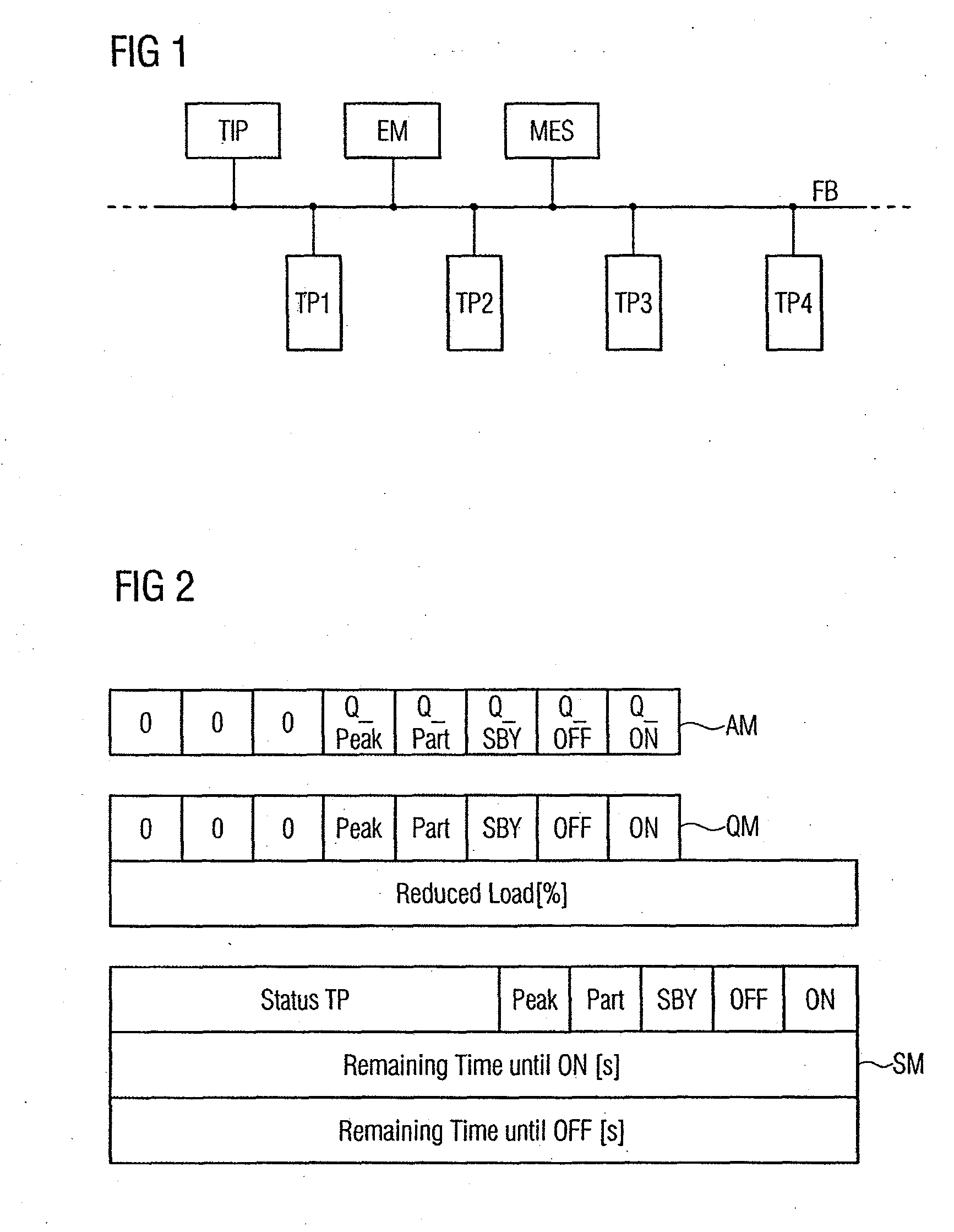
[0028]FIG. 1 shows a schematic block diagram of an industrial automation arrangement, such as a production system, in which automation components (TP1, . . . , TP4) (subprocesses) are arranged via a data network field bus system (FB), the automation components (TP1, . . . , TP4) each representing a subprocess to be controlled. Consequently, a respective subprocess is controlled by a respective automation component (TP1, . . . , TP4). In addition, the energy supply (Totally Integrated Power (TIP)), an energy management device (EM) with a control component and a planning entity (Manufacturing Execution System (MES)) are integrated in the automation arrangement using the data network (FB) and using an infrastructure (for example, energy supply lines) which is not illustrated for purposes of clarity.

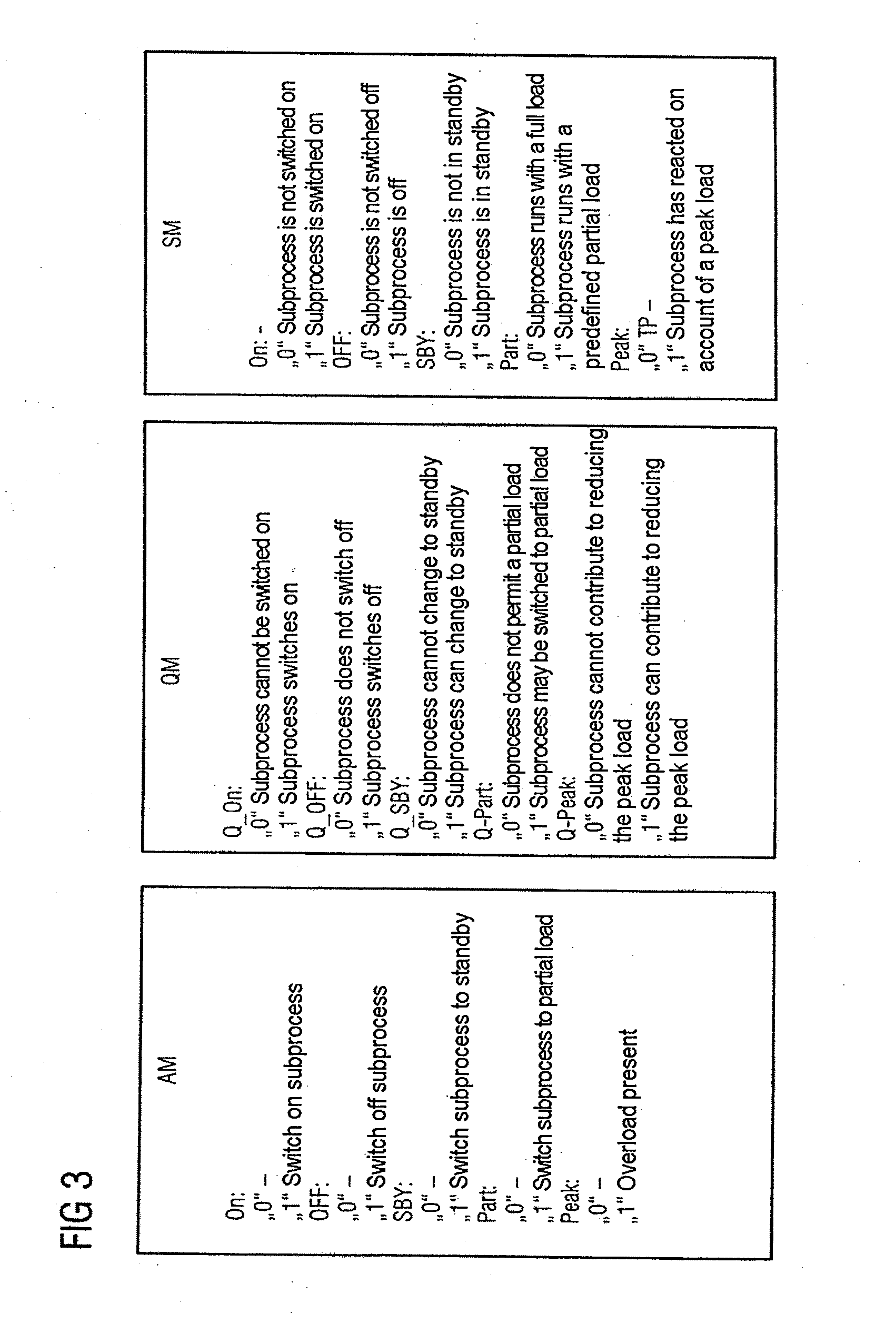
[0029]The control component is configured for message-based interchange of control and state data relating to the settings of an energy-saving profile integrated in each of the automation co...


PUM


Abstract

A control component and method for an energy management unit (EM) in an industrial automation arrangement which is configured to control one of a process, a subprocess and a system part of the industrial automation arrangement. Here, the control component is configured to detect the energy consumption of at least one part of the industrial automation arrangement, and the control component is configured to relate the detected energy consumption to at least one stored specification. The control component is also configured to generate a request for at least one automation component as the result of the relating operation. The control component is configured to transmit a message containing the request to the automation component and to receive an acknowledgement message from this automation component, where the request is directed to changing an operational state of one of the process, subprocess and system part that is controlled by the automation component.

Description

BACKGROUND OF THE INVENTION[0001]1. Field of the Invention[0002]The invention relates to control systems and, more particularly, to a method and control component for an energy management unit in an industrial automation arrangement.[0003]2. Description of the Related Art[0004]Usually, industrial automation arrangements (also called programmable logic controllers (PLC)) comprise a multiplicity of automation components that are connected to one another by a data network, such as a field bus system. The automation components comprise, for example, sensors and actuators, where the actuators mentioned are particularly used to control industrial processes, subprocesses of industrial processes, production systems or the like. The automation components also include control devices, such as CPUs and controllers, which are used to process the signals detected by the sensors in a program-controlled manner, and to control a production system or another process or subprocess by driving the actu...

Claims


Application Information

Patent Timeline
Patent Type & Authority Applications(United States)
IPC IPC(8): G06F19/00
CPCG05B19/042Y02P80/40Y02P80/114G05B2219/2639Y02P80/10
Inventor AUGUST, JOACHIMBROUSEK, NORBERTJOHSSEN, OLIVEROHLMANN, JOACHIM
Owner SIEMENS AG
Why Eureka
Try Eureka