Rodent management system having a housing with an entry opening

a management system and rodent technology, applied in the field of rodent management systems, can solve the problems of difficult or non-feasible reconfiguration, difficult and time-consuming removal of debris from prior systems, and inability to remove debris in a piecemeal fashion, etc., to achieve convenient reconfiguration of bait, easy to clean the station, and good weather resistance

Inactive Publication Date: 2010-07-08
BASF CORP
View PDF102 Cites 26 Cited by
  • Summary
  • Abstract
  • Description
  • Claims
  • Application Information

AI Technical Summary

Benefits of technology

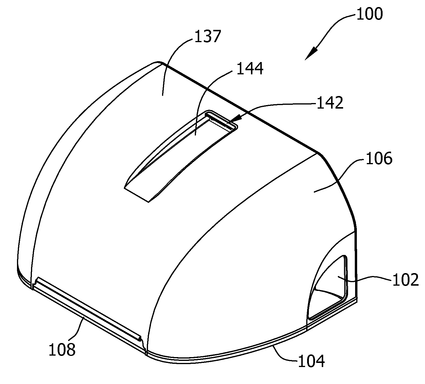
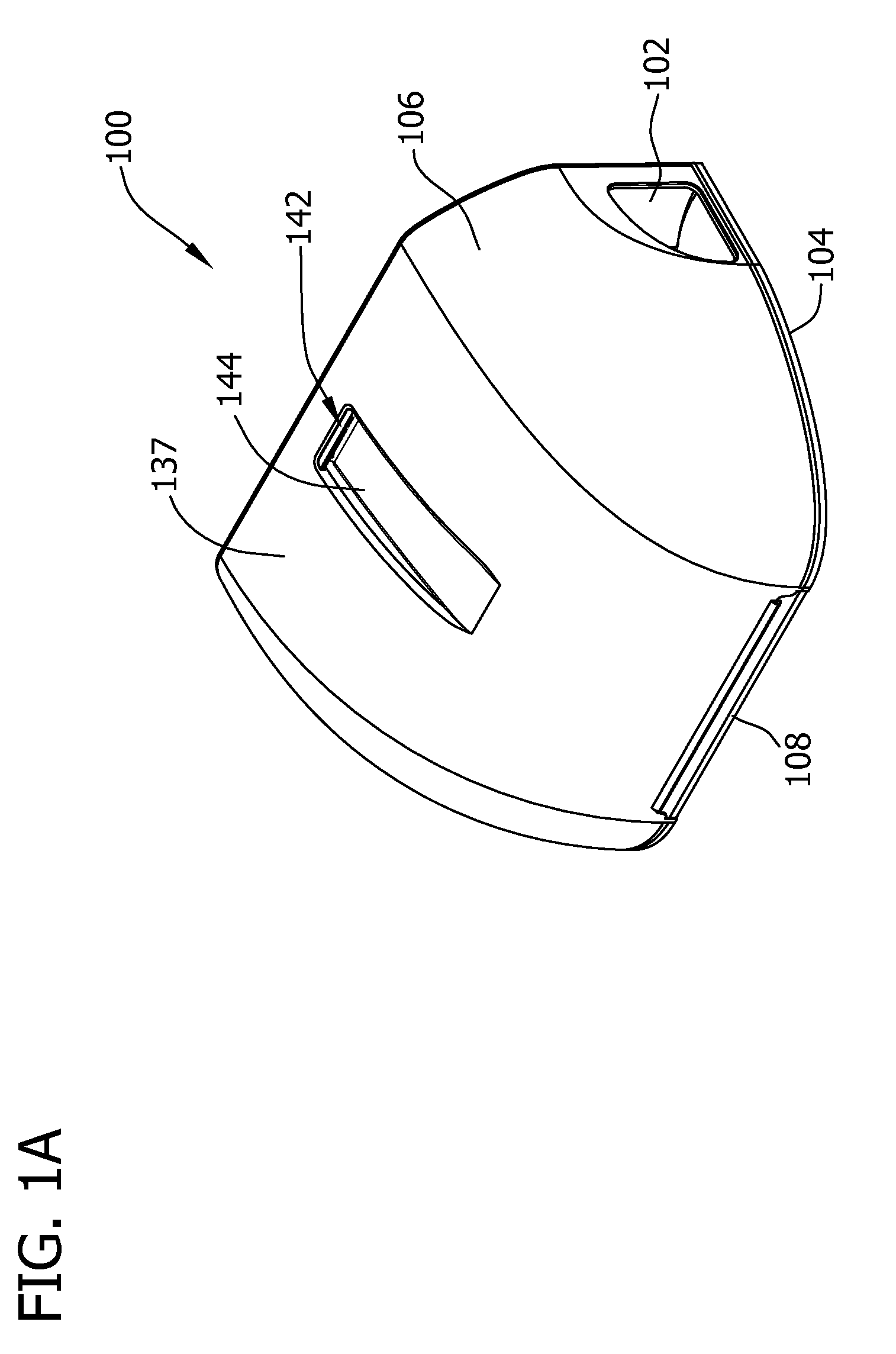
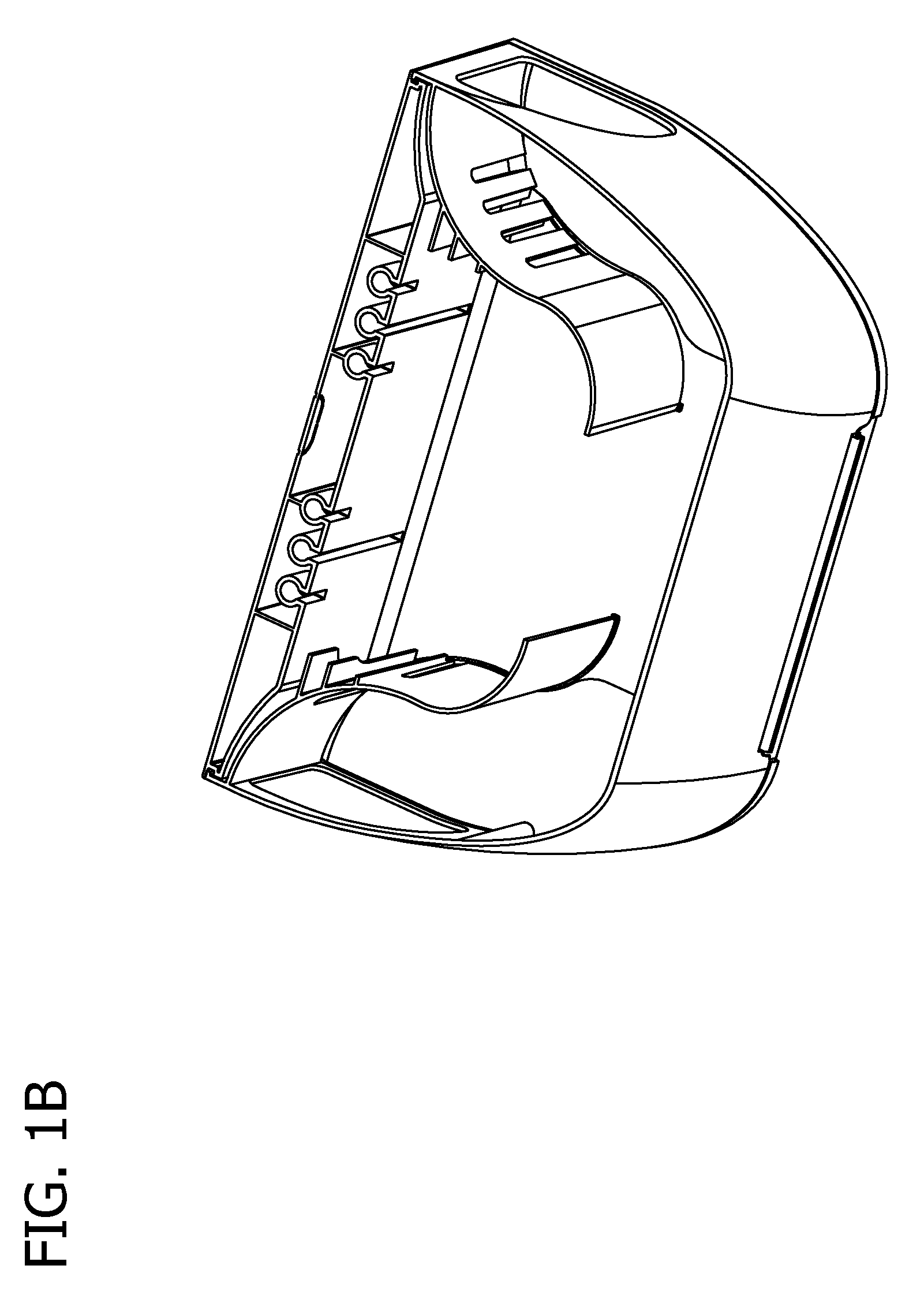
[0006]In another aspect, a rodent management station generally comprises a housing having an interior space and including a base and a lid together at least in part defining the interior space of the housing, the base comprising a floor panel having an inner surface. The lid is positionable relative to the base between a closed configuration of the station in which the interior space is substantially enclosed, and an opened configuration of the station in which the interior space is accessible for servicing. The housing has an entry opening through which rodents enter the interior space of the housing. The housing further has an internal partition structure configured to partition the interior space of the housing into a bait chamber having an entryway spaced from the entry opening of the housing, and a pathway defined at least in part by the partition structure and extending away from the at least one entry opening to the entryway of the bait chamber. The partition structure is connected to the lid of the housing for conjoint movement with the lid relative to the base upon movement of the lid to the opened configuration of the station. In the closed configuration of the station at least a portion of the partition structure is in closely spaced relationship with the inner surface of the floor panel to inhibit rodents from crawling under the portion of the partition structure.

Problems solved by technology

Removal of debris from prior systems is tedious and time-consuming due to their construction, i.e., having a base or floor and an upstanding perimeter wall.
Thus, debris can only be removed in a piecemeal fashion, or by overturning the base, or by suctioning debris from the station.
The placement of bait or traps within the housing is often fixed as well, rendering reconfiguration difficult or non-feasible.

Method used


Image

  • Rodent management system having a housing with an entry opening
  • Rodent management system having a housing with an entry opening
  • Rodent management system having a housing with an entry opening

Examples


first embodiment

[0182]While not visible in the drawings, in some embodiments at least a portion of the inner surface 1118 of the bottom panel 1114 of the station 1100 housing (i.e., the floor of the housing) may be textured in the same manner as the inner surface 118 of the bottom panel 114 of the station 100 housing of the As illustrated in FIGS. 38 and 39, one or more demarcations 1111 may be provided on the inner surface 1118 of the bottom panel 1114 to indicate where the interior panels 1112 are located in the closed configuration of the station 1100. The demarcations 1111 facilitate proper alignment of the bait and traps within the bait chamber 1138 of the station 1100 housing to avoid interference with lid 1106 and in particular the interior panels 1112 upon closing the lid. The demarcations 1111 may be in any suitable form such as, without limitation, indicia, different coloring from the inner surface 1118 of the bottom panel 1114, labels, different texturing from the texture of the inner s...

second embodiment

[0183]The bait system and in particular the bait supports 1158 of the rodent management station 1100 of this embodiment are also different from the bait supports 158 of the previous station 100. Suitable bait support configurations for this second embodiment are illustrated in FIGS. 38-55, and in particular with respect to such supports for retaining bait blocks 1156 or other bait in generally vertical (e.g., stacked) configurations. It is understood, however, that the bait supports of this embodiment may also be configured to retain bait blocks 1156 or other bait in a general horizontal alignment as in the previous embodiment without departing from the scope of this invention.

[0184]As one example, with particular reference to FIG. 41, one suitable bait support 1158 is illustrated in the form of a bait tray 1322 having upstanding walls 1324 that extend upwardly from a horizontal bottom 1326 of the bait tray 1322 to form a trough 1330. A vertical wall 1328 is coupled to and extends u...

third embodiment

[0235]In addition to the differences in overall dimensions between the stations 100 and 300, the rodent management station 300 differs in one aspect from the previously described embodiments in that the bait is positioned differently within the station 300. For example, in this third embodiment bait is instead supported by bait support structure depending from the lid 306 above the bait chamber 338.

[0236]One or more bait supports 358 may be utilized for positioning and retaining bait within the bait chamber 338. FIGS. 85-89 illustrate two different types of exemplary bait supports 358. The bait supports 358 function in the same general manner and are coupled at one or both of their ends to the lid 306. The bait supports in turn pass through a hole in each of the bait blocks (or a hole in a single bait block) —the hole being centrally located in the bait block although the hole need not be centrally located to remain with the scope of the invention. It is also understood that the bai...


PUM


Abstract

A rodent management station includes a housing having a base and a lid together at least in part defining an interior space. The housing has an entry opening and an internal partition structure configured to partition the interior space of the housing into a bait chamber having an entryway spaced from the entry opening. A pathway is defined at least in part by the partition structure and extends away from the at least one entry opening to the entryway of the bait chamber. The partition structure has at least one through-opening therein other than at the bait chamber entryway to provide open communication between the pathway and the bait chamber other than at the bait chamber entryway. The at least one through-opening is sized substantially smaller than the housing entry opening and the bait chamber entryway to inhibit rodents against entering the bait chamber at the at least one through-opening.

Description

CROSS-REFERENCE TO RELATED APPLICATION[0001]This application is a divisional application of U.S. patent application Ser. No. 12 / 671,172, filed Jan. 28, 2010, which is hereby incorporated by reference in its entirety.BACKGROUND[0002]The embodiments described herein are generally related to rodent management systems, and more specifically to systems for trapping and / or killing rodents. Rodent bait stations typically include a housing having an internal chamber and toxic baits or other trapping devices disposed in the chamber for controlling rodents (e.g., rats and mice). The housing is designed to inhibit non-targeted animals (e.g., dogs, cats) and unauthorized individuals (e.g., children) from coming into contact with the baits or the devices (e.g., trap mechanisms, such as, but not limited to snap traps, live catch traps, or snares). Often, the housing has a generally low-profile. That is, the height of the housing is only slightly taller than an average-sized rodent in a prone (e.g...

Claims


Application Information

Patent Timeline
Patent Type & Authority Applications(United States)
IPC IPC(8): A01M25/00A01M23/00A01M23/08
CPCA01M25/004A01M25/00A01M23/02
Inventor CINK, JAMES H.BERGER, JONATHAN D.MANN, BRIAN JAMESMARSHALL, EDWARD FRANCISMORAN, HENRY WAYNEPOLING, JAMES DAVID
Owner BASF CORP
Why Eureka
Try Eureka