Measurement apparatus and method thereof

a technology of measurement apparatus and measurement device, which is applied in the direction of measurement device, antenna radiation diagram, instrument, etc., can solve the problems of labor efficiency degradation and difficulty in antenna rotation

Inactive Publication Date: 2010-07-08
KK TOSHIBA
View PDF0 Cites 30 Cited by
  • Summary
  • Abstract
  • Description
  • Claims
  • Application Information

AI Technical Summary

Problems solved by technology

However, when the antenna has a fine feeding structure such as being fed by a probe, it is difficult for the antenna to rotate connecting a needle ...

Method used


Image

  • Measurement apparatus and method thereof
  • Measurement apparatus and method thereof
  • Measurement apparatus and method thereof

Examples


first embodiment

Description of the First Embodiment

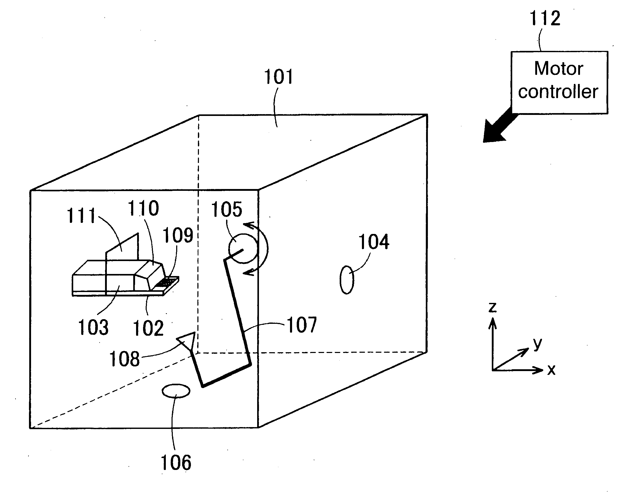
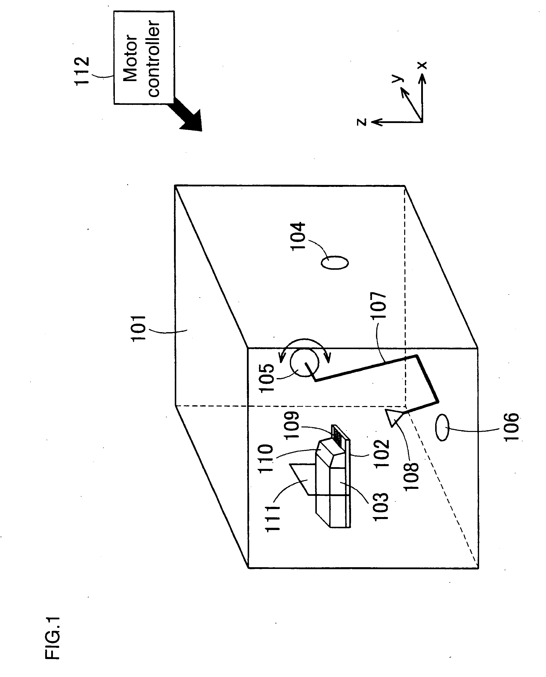
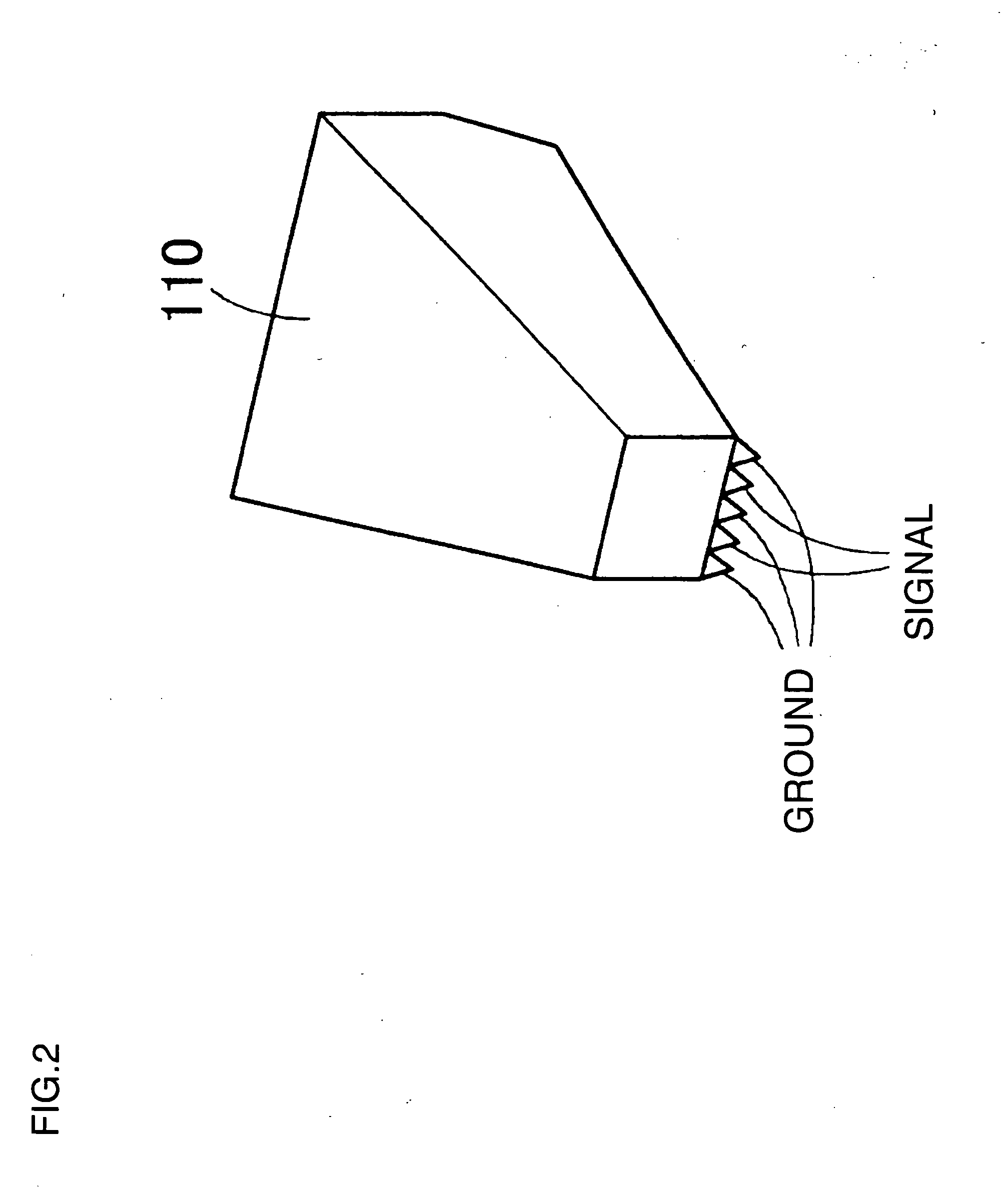
[0049]As shown in FIG. 1, a measurement apparatus includes an anechoic chamber 101, a DUT (Device Under Test) board 102, a probe hold 103, rotation units 104-106, and a feeding arm 107.

[0050]The anechoic chamber 101 has a plural of walls (six walls exist in FIG. 1). Each wall is covered with radio wave absorber (not shown). The radio wave absorber may be made of urethane absorbing carbon. The radio wave absorber may have a wave-shaped or a pyramid-shaped on its surface. An aperture 111 is opened at an almost center of one of the walls. The several walls (three walls in FIG. 1) have the rotation units 104-106, respectively. The rotation units 104-106 can hold the feeding arm 107. At least one wall has a door (not shown) which is able to be opened and closed. Size of the anechoic chamber 101 depends on a frequency of radio wave.

[0051]The DUT board 102 is placed as that a part of the DUT board 102 is inserted into the anechoic chamber 101 through the ...

second embodiment

Description of the Second Embodiment

[0080]As shown in FIG. 20, a measurement apparatus is almost same as that of the first embodiment except that it further includes a microscope 201 and a support unit 202. The support unit 202 supports the microscope 201. The support unit 202 includes a shifting unit in order to shift the microscope 201 in a vertical direction. The sifting unit performs micro adjustment or coarse adjustment about how long the microscope 201 is shifted. The support unit 202 may include the shifting unit in order to shift the microscope 201 in a horizontal direction.

[0081]An aperture 203 is opened in top of the anechoic chamber 101 in order to set the microscope 201 inside the anechoic chamber 101. The aperture 203 is formed above the measured antenna 109 placed on the DUT board 102.

[0082]Other else components (except for the microscope 201, the support unit 202 and the aperture 203) are same as them of the first embodiment. Therefore, explanations about them are ski...


PUM


Abstract

A measurement apparatus includes an anechoic chamber, a DUT board, rotation units, and a feeding arm. The anechoic chamber has inner-walls. Each inner-wall is covered with a radio wave absorber. One of the inner-wall is a first wall with an aperture and the other inner-walls are second walls. The DUT board holds a first antenna to be measured with radiation property and a probe to detect a signal from the first antenna. A part of the DUT board is inserted into the anechoic chamber through the aperture opened in the first wall. One end of the feeding arm holds a second antenna radiating a radio wave to the first antenna in the anechoic chamber. Each rotation unit provides on each second wall and is selectively attached to the other end of the feeding arm for rotating the second antenna and for feeding to the second antenna.

Description

CROSS-REFERENCE TO RELATED APPLICATIONS[0001]This application is based upon and claims the benefit of priority from the Japanese Patent Application. No. 2009-000762, filed on Jan. 6, 2009, the entire contents of which are incorporated herein by reference.BACKGROUND OF THE INVENTION[0002]1. Field of the Invention[0003]The present invention relates to a measurement apparatus and a method thereof.[0004]2. Description of the Related Art[0005]One of the techniques to measure radiation property of an antenna in three dimension is disclosed in JP-A 2004-7233249 (KOKAI). In this reference, an antenna to be measured rotates in an anechoic chamber.[0006]However, when the antenna has a fine feeding structure such as being fed by a probe, it is difficult for the antenna to rotate connecting a needle of the probe into a chip implemented the antenna.[0007]Other technique to measure radiation property is disclosed in JP-A 2006-53010 (KOKAI). In this reference, the antenna is fixed and connected to...

Claims


Application Information

Patent Timeline
IPC IPC(8): G01R29/08
CPCG01R29/10G01R29/105
Inventor ITO, TAKAYOSHITSUTSUMI, YUKAKOOBAYASHI, SHUICHISHOKI, HIROKI
Owner KK TOSHIBA
Why Eureka
Try Eureka