
System and method for multi-path simulation

a multi-path simulation and simulation system technology, applied in the field of multi-path simulation, can solve the problems of increasing the complexity and instability of signal transceiving, affecting the performance of the signal, and affecting the quality of the signal, so as to reduce the strength of the reflected signal and simulate the attenuation

Inactive Publication Date: 2007-05-29
ACETON TECH
View PDF9 Cites 22 Cited by
  • Summary
  • Abstract
  • Description
  • Claims
  • Application Information

AI Technical Summary

Benefits of technology

Enables reliable simulation of multi-path wireless signal transmission in a controlled environment, providing accurate testing results without spatial limitations and allowing for the measurement of antenna diversity gain, thereby improving product development for wireless communication devices.

Problems solved by technology

The phenomenon results in the constructive or destructive interference, and phase shifting of the signal, caused by the refraction, and the reflection from objects, such as buildings and obstacles.
The phenomenon exists in most real environments and would increase the complexity and instability of signal transceiving.
It is very hard to provide reliable testing reports for the products used in the real environments because external EMI and superfluous reflection paths cannot be avoided in these environments.
Moreover, the testing operation may be limited by the space characteristics of these environments.
In some cases, channel emulators are used to simulate the real environments, but they fail to test the important feature of antenna diversity since they operate in the cable mode and antennas of communication devices to be tested are bypassed.

Method used


Image

  • System and method for multi-path simulation
  • System and method for multi-path simulation
  • System and method for multi-path simulation

Examples


Embodiment Construction

[0016]This section will explain the present invention in detail with preferred embodiments and appended drawings, and also describes an application of the present invention, i.e. the measurement of the diversity gain of a wireless communication device.

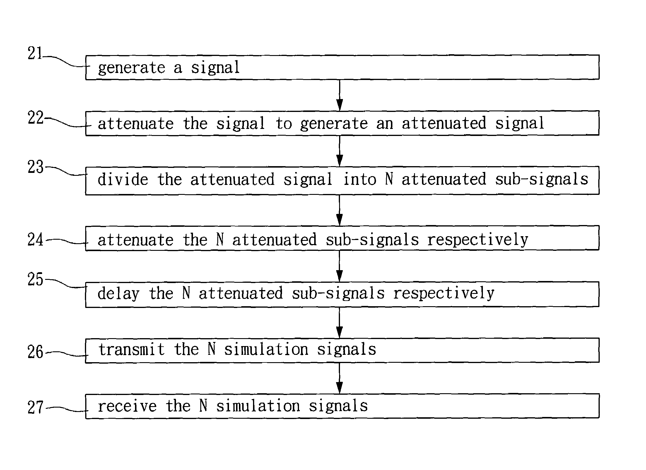
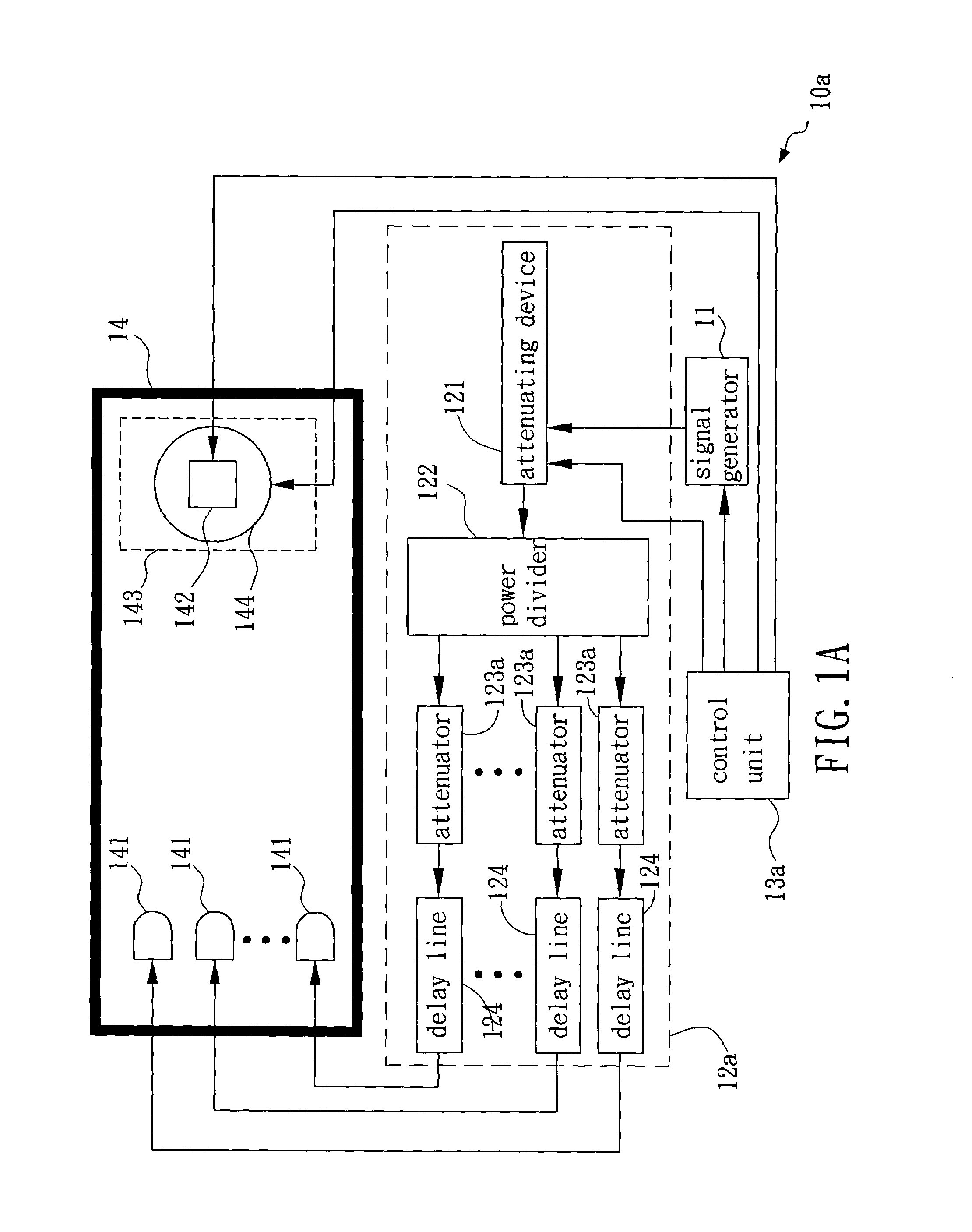
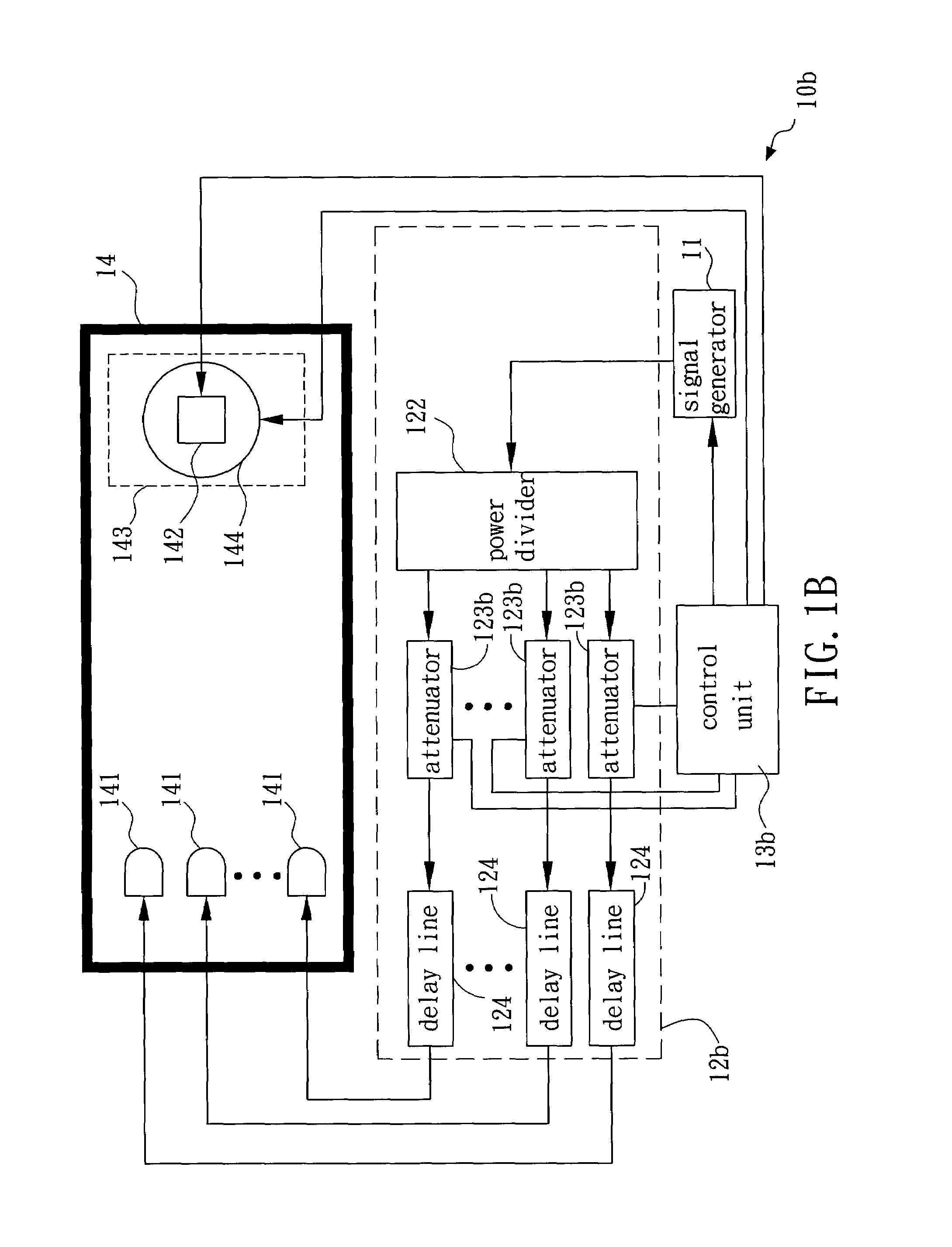
[0017]FIG. 1A is a block diagram showing a preferred embodiment of the system for multi-path simulation according to the present invention. In FIG. 1A, the system 10a for multi-path simulation is used to simulate a wireless communication space with N paths (N is an integer larger than one). The system 10a includes a signal generator 11 for generating a signal and a signal-simulating unit 12a, coupled to the signal generator 11, for dividing and adjusting the signal into N simulation signals in N ways to simulate attenuations and delays resulted from the transmission of the signal in the N paths. The system also includes a control unit 13a, coupled to the signal generator 11, for controlling the generation of the signal. The system also...


PUM


Abstract

The present invention provides a system and method for multi-path simulation that employs a shielded anechoic chamber to avoid external electromagnetic interference and other uncontrollable transmission paths generated in testing, and divides and adjusts a signal into multiple simulation signals to simulate the attenuations and delays generated in multi-path transmission of the signals. The shielded anechoic chamber includes a turntable, controlled by a control unit, for carrying a wireless communication device to be tested and for changing the reception azimuth of the device, thereby measuring the electric wave transceiving of the device.

Description

BACKGROUND OF THE INVENTION[0001](a). Field of the Invention[0002]The present invention relates in general to multi-path simulation, and more particularly to a system and method that employs a shielded anechoic chamber to avoid external electromagnetic interference (EMI), and divides a signal into multiple simulation signals to simulate the signal attenuation and delay during multi-path transmission.[0003](b). Description of the Prior Arts[0004]In recent years, cellular phones and wireless local area networks (WLAN) are in widespread use with the rapid development of wireless communication technologies. In comparison with the signal transmission with a single physical path, the wireless signal transmission has an intrinsic multi-path phenomenon. The multi-path phenomenon means the wireless signal reaching the receiving antenna by two or more paths. The phenomenon results in the constructive or destructive interference, and phase shifting of the signal, caused by the refraction, and ...

Claims


Application Information

Patent Timeline
Patent Type & Authority Patents(United States)
IPC IPC(8): H04B17/00
CPCH04B17/20
Inventor LIU, I-RU
Owner ACETON TECH
Learn More