Over-the-air test

a test and over-the-air technology, applied in the field of over-the-air testing, can solve the problems of interference with the radio connection, different durations and strengths of the received signal,

Active Publication Date: 2011-08-04
KEYSIGHT TECH SINGAPORE (SALES) PTE LTD
View PDF5 Cites 21 Cited by
  • Summary
  • Abstract
  • Description
  • Claims
  • Application Information

AI Technical Summary

Benefits of technology

[0008]An object of the invention is to provide an improved solution. According to an aspect of the invention, there is provided a method of communicating with an electronic device under test through a simulated radio channel of an emulator. The method comprises optimizing a cost function of a theoretical spatial cross correlation and a spatial correlation obtained with antenna elements for determining weights of the antenna elements; and forming, on the basis of the weights, a beam of a signal of at least one path of a simulated radio channel with at least two antenna elements of a plurality of the antenna elements coupled to an emulator in an anechoic chamber.

Problems solved by technology

When a radio frequency signal is transmitted from a transmitter to a receiver, the signal propagates in a radio channel along one or more paths having different angles of arrivals, signal delays and powers, which causes fadings of different durations and strengths in the received signal.
In addition, noise and interference caused by other transmitters interfere with the radio connection.

Method used


Image

  • Over-the-air test
  • Over-the-air test
  • Over-the-air test

Examples


Embodiment Construction

[0038]Channel impulse responses and an optimization of the antenna weights in OTA may be formed so that an accurate correlation, an angle of arrival and polarization properties may be possible for a DUT.

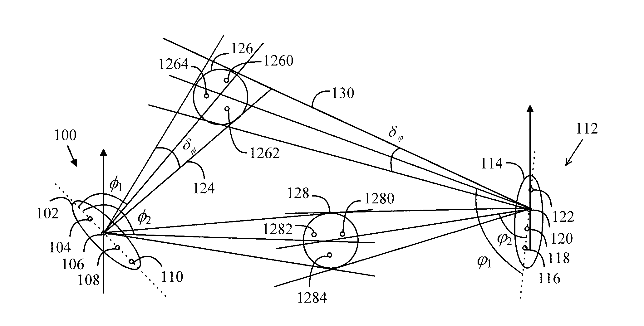
[0039]FIG. 1 illustrates propagation of a radio signal between a transmitter and a receiver. The transmitter 100 may comprise an antenna 102 of at least one antenna element 104 to 110. The antenna may be, for example, ULA (Uniform Linear Array) antenna where the spacing between the antenna elements is constant, for example half a wavelength of the radio signal. In this example, the transmitter 100 may be a base station of a radio system. Correspondingly, the receiver 112 may comprise an antenna 114 of at least one antenna element 116 to 122. In this example, the receiver 112 may be a subscriber terminal of a radio system. When the transmitter 100 transmits a radio signal, a transmission beam 124 may be directed to an angle φ1 and its angle spread may be δφ which may be xδφstd, where ...


PUM


Abstract

A testing system optimizes a cost function of a theoretical spatial cross correlation and a spatial correlation obtained with antenna elements for determining weights of the antenna elements, and forms a beam of a signal of at least one path of a simulated radio channel with at least two antenna elements of a plurality of antenna elements coupled to an emulator in an anechoic chamber. The at least two antenna elements are capable of polarizing the beam in a known manner.

Description

CROSS-REFERENCE TO RELATED APPLICATIONS[0001]This application is a National Phase application of International Application No. PCT / FI2008 / 050155 filed Feb. 25, 2009, which claims priority to PCT / FI2008 / 050554, filed Oct. 6, 2008, which are incorporated herein by reference in their entirety.BACKGROUND[0002]1. Field[0003]The invention relates to an over-the-air testing of a device in an anechoic chamber.[0004]2. Description of the Related Art[0005]When a radio frequency signal is transmitted from a transmitter to a receiver, the signal propagates in a radio channel along one or more paths having different angles of arrivals, signal delays and powers, which causes fadings of different durations and strengths in the received signal. In addition, noise and interference caused by other transmitters interfere with the radio connection.[0006]A transmitter and a receiver can be tested using a radio channel emulator emulating real circumstances. In a digital radio channel emulator, a channel ...

Claims


Application Information

Patent Timeline
Patent Type & Authority Applications(United States)
IPC IPC(8): H04B17/00
CPCH01Q21/20H04B17/3912H01Q25/00G01R29/08H04B17/00
Inventor KYOSTI, PEKKANUUTINEN, JUKKA-PEKKA
Owner KEYSIGHT TECH SINGAPORE (SALES) PTE LTD
Why Eureka
Try Eureka