Apparatus for measuring read range between RFID tag and reader

a technology of radio frequency identification and reading range, which is applied in the direction of resistance/reactance/impedence, measurement devices, instruments, etc., can solve the problems of inability to move a system after the installation of the system, inability to measure an accurate read range, and inability to accurately measure the read range. , to achieve the effect of accurate measurement, accurate determination, and easy mobility and extendability

Inactive Publication Date: 2006-11-23
ELECTRONICS & TELECOMM RES INST
View PDF8 Cites 22 Cited by
  • Summary
  • Abstract
  • Description
  • Claims
  • Application Information

AI Technical Summary

Benefits of technology

[0007] To solve the above and / or other problems, the present invention provides an apparatus for measuring a read range between an RFID tag and a reader which provides an electromagnetic anechoic chamber having easy mobility and extendability and accurately determines whether the RFID tag is read according to the position and analyses the pattern of an antenna by accurately measuring a field strength according to the distance and angle between the RFID tag and the reader.

Problems solved by technology

The former method cannot measure an accurate read range while the latter method is difficult to measure an accurate read range because the absorption rate of an electromagnetic absorbent varies according to the position of measurement in an antenna chamber.
Also, in the latter method, moving a system after the system is installed is not possible and extension of the antenna chamber is difficult.

Method used


Image

  • Apparatus for measuring read range between RFID tag and reader
  • Apparatus for measuring read range between RFID tag and reader
  • Apparatus for measuring read range between RFID tag and reader

Examples


Embodiment Construction

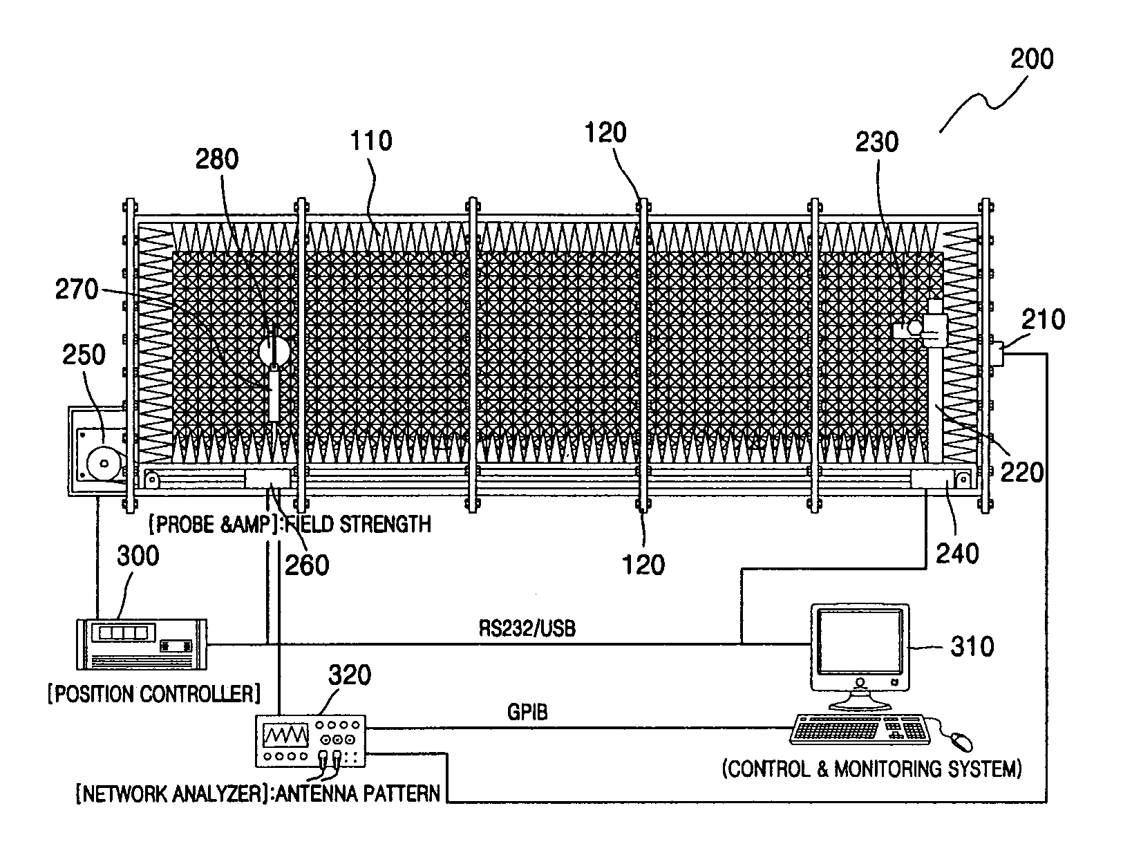
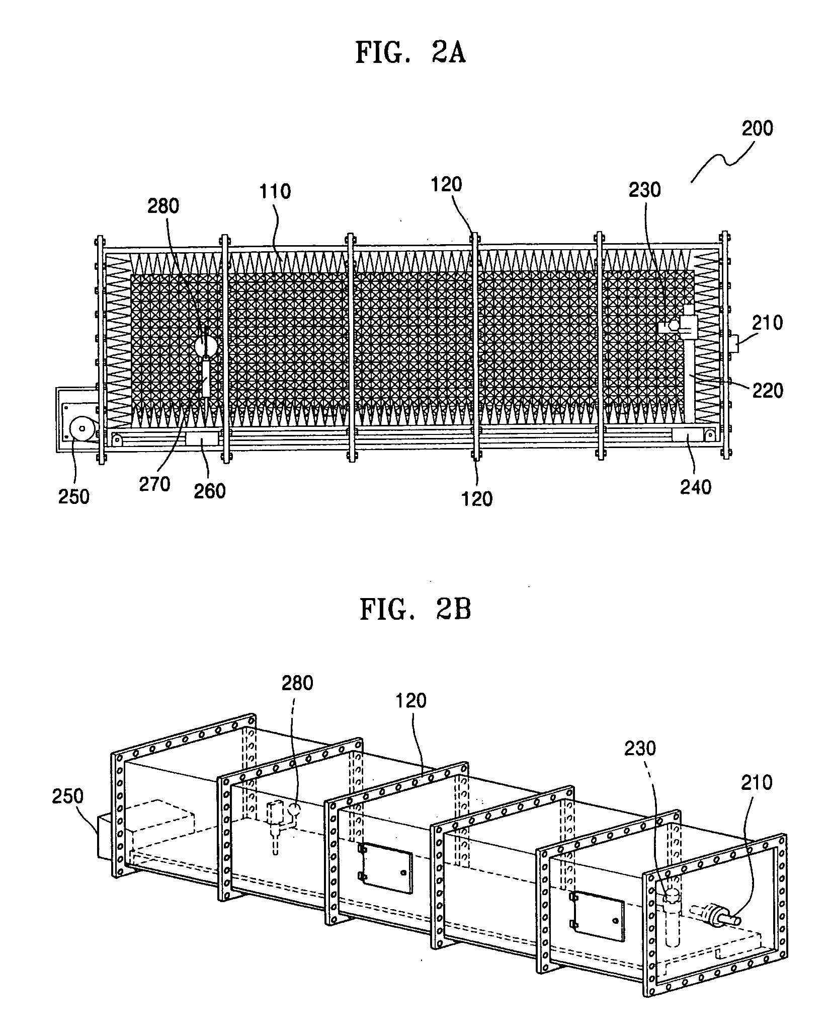
[0013] An anechoic chamber in which an electromagnetic wave is not echoed is necessary for accurately measuring a read range between a tag and a reader. The present invention does not provide an electromagnetic anechoic chamber having a fixed size, but provide an electromagnetic anechoic chamber formed by assembling a plurality of unit cells for the facilitation of mobility and extendability.

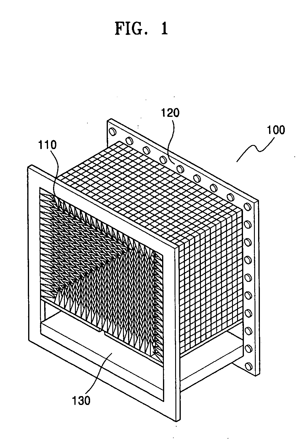
[0014]FIG. 1 shows a unit cell 100 of an electromagnetic anechoic chamber according to an embodiment of the present invention. Referring to FIG. 1, the unit cell 100 includes an electromagnetic absorbent 110 that is based on carbon, a cell connection frame 120, and a tag support portion moving path 130. The electromagnetic absorbent 110 is located oh an inner wall of the unit cell 100 to absorb an electromagnetic wave. The cell connection frame 120 is a connection member to connect cells so that a user can connect a desired number of the unit cells 100 in a series. The tag support portion movin...


PUM


Abstract

Provided is an apparatus for measuring a read range between a tag and a reader, which includes an electromagnetic anechoic chamber formed by connecting at least one unit cell in a row, the unit cell having an electromagnetic wave absorbent provided on an inner wall of each unit cell, an electromagnetic generation portion located at the unit cell at an end of the electromagnetic anechoic chamber and transmitting an electromagnetic wave through an antenna, and an electromagnetic measurement portion which measures a field strength of the electromagnetic wave transmitted from the electromagnetic generation portion using an electric field probe moving in the electromagnetic anechoic chamber.

Description

CROSS-REFERENCE TO RELATED PATENT APPLICATIONS [0001] This application claims the benefits of Korean Patent Application No. 10-2005-0041031, filed on May 17, 2005, and Korean Patent Application No. 10-2005-0067821, filed on Jul. 26, 2005, in the Korean Intellectual Property Office, the disclosure of which are incorporated herein in their entirety by reference. BACKGROUND OF THE INVENTION [0002] 1. Field of the Invention [0003] The present invention relates to an apparatus for measuring a read range between an RFID (radio frequency identification) tag and a reader, and more particularly, to an apparatus for measuring an accurate field strength according to the distance between an RFID tag and a reader using an electromagnetic anechoic chamber having easy mobility and extendability. [0004] 2. Description of the Related Art [0005] A conventional method for measuring a read range between an RFID tag and a reader includes a method for manually measuring a distance between an RFID tag and...

Claims


Application Information

Patent Timeline
Patent Type & Authority Applications(United States)
IPC IPC(8): G01R27/00
CPCG01R29/0814G01R31/2822G01R29/0871G01R29/0821
Inventor LEE, JONG MOONKIM, NAE SOOPYO, CHEOL SIGCHAE, JONG SUK
Owner ELECTRONICS & TELECOMM RES INST
Why Eureka
Try Eureka