To systems for acoustic diffusion

a technology for acoustic diffusion and systems, applied in the direction of transducer circuits, transducer casings/cabinets/supports, transducer circuit damping, etc., can solve the problems of loss of efficiency, loss of efficiency of transducers, and maximum dissipation of amplification devices, etc., to achieve simple and practical installation

Active Publication Date: 2010-07-08
LASTRUCCI CLAUDIO
View PDF4 Cites 153 Cited by
  • Summary
  • Abstract
  • Description
  • Claims
  • Application Information

AI Technical Summary

Benefits of technology

[0020]According to a first aspect, an object of the present invention is to provide a power amplification module for driving an electro-acoustic transducer for acoustic diffusers that is particularly simple and practical to install.
[0022]In this way, on the one hand there is obtained an easy assembly and a high simplicity of intervention for removal and maintenance of the amplifier unit. On the other hand, said unit does not take up space of the diffuser that could affect in an unforeseeable way or in a way that is hard to foresee the acoustic performance of the diffuser itself. The front arrangement, in the mobile diaphragm of the transducer, moreover presents the advantage of exploiting the displacement of air caused by the mobile diffusion diaphragm for facilitating dissipation of the heat generated by the power components within the amplifier unit. For said purpose, according to an advantageous embodiment of the invention, a finning can be provided for facilitating dissipation of heat.

Problems solved by technology

In amplification systems that operate in the conditions of electrical phase difference between output voltage and current there arise conditions of loss of efficiency, and in the case of purely reactive loads (real output power zero) the dissipation of the amplification device is maximum.
As regards the efficiency of electro-acoustic conversion, the presence of a real part in the equivalent circuit of the transducer implies a loss of efficiency of the transducer and in the case of high powers of electrical-acoustic conversion sets a limit for thermal dissipation of the moving coil.
This type of transducer has for the amplifier a load with ample reactive parts and, from what has been said above, is not suitable where amplifiers of a linear type are used.
However, a transducer made with the criterion of optimizing only the energy aspects presents considerable disadvantages in applicability in standard operating configurations.

Method used


Image

  • To systems for acoustic diffusion
  • To systems for acoustic diffusion
  • To systems for acoustic diffusion

Examples


Embodiment Construction

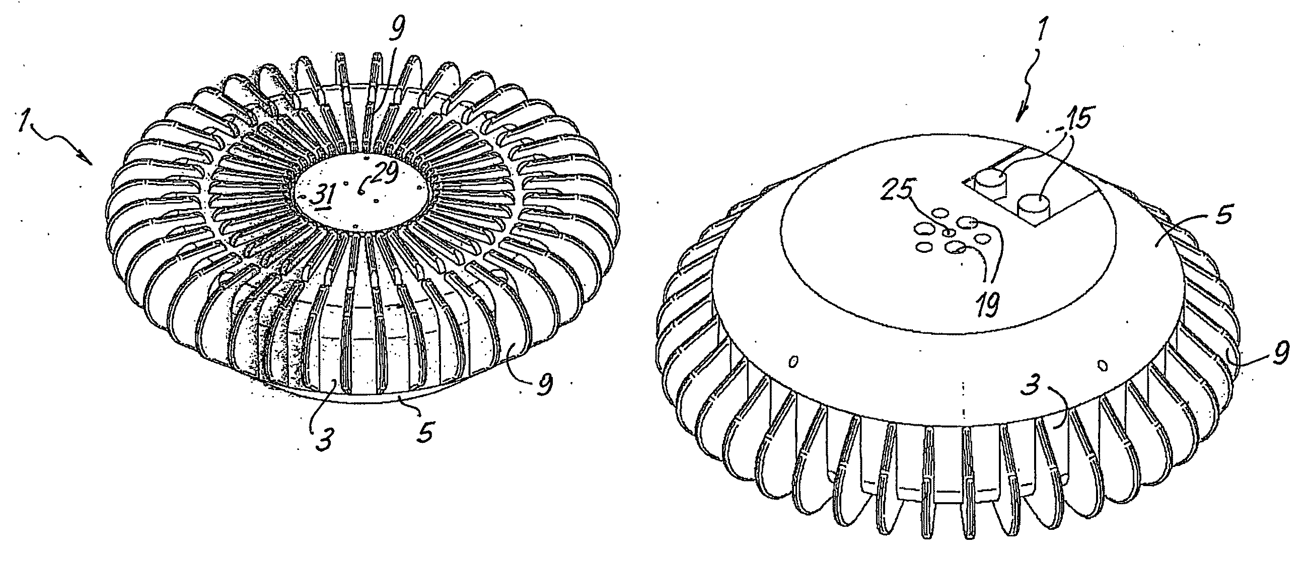
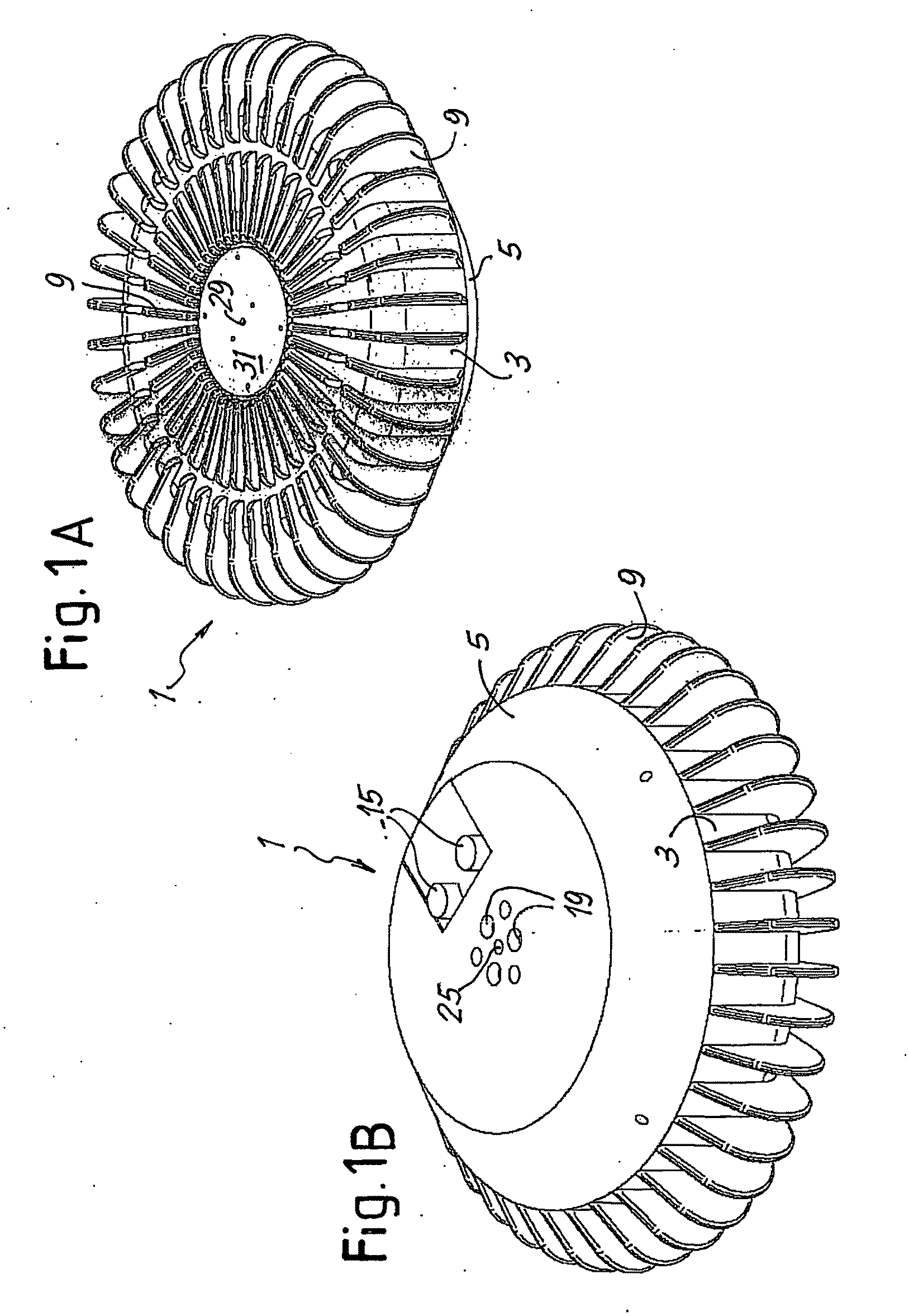
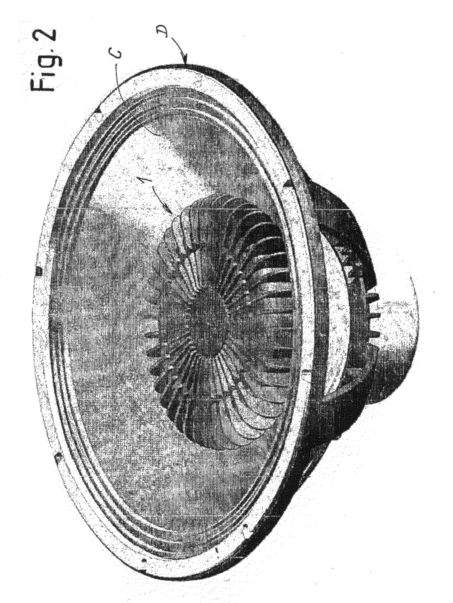
[0043]With initial reference to FIGS. 1 to 5, the structure of the amplifying and processing unit associated to an acoustic transducer and the modalities of application to the transducer will first be described. The unit is designated as a whole by 1 and, according to an advantageous embodiment, is applied within the hollow conical space delimited by the mobile diaphragm or cone C of an acoustic diffuser D.

[0044]The unit 1 is enclosed within a housing or container delimited by a front shell 3 and by a rear shell 5, joined to one another (FIG. 4) by means of screws 7 provided, in adequate number, for example four, around the perimetral development of the container 3, 5. The container has a substantially axisymmetrical development, and the axis of symmetry is designated by A-A. Arranged on the front shell 3 are cooling fins 9, which have a radial development with respect to the axis A-A. The fins 9 have the purpose of dissipating the heat generated by the electronic components, especi...


PUM


Abstract

Described is a unit for amplifying and processing audio signals for driving an electro-acoustic transducer (D), comprising: an input for audio signals; a processor for audio signals (107); an output for a signal for driving said electro-acoustic transducer; and an input for at least one operating quantity of the electro-acoustic transducer. The audio-signal processor is programmed for setting a series of parameters defining a transducer to be emulated, the parameters of which define a model of the transducer to be emulated. The input audio signal is processed on the basis of said at least one operating quantity of the electro-acoustic transducer to obtain a behavior of the electro-acoustic transducer that emulates the transducer defined by said series of parameters set.

Description

TECHNICAL FIELD[0001]The present invention relates to improvements to devices for acoustic diffusion. More in particular, the present invention relates to improvements to the methodologies for power amplification, audio processing, and control of acoustic transducers.STATE OF THE ART[0002]A traditional audio amplification system, of a linear type, finds its theoretical maximum of conversion efficiency when the maximum of the output voltage and current are perfectly in phase (this occurs only in the case of purely resistive loads).[0003]In amplification systems that operate in the conditions of electrical phase difference between output voltage and current there arise conditions of loss of efficiency, and in the case of purely reactive loads (real output power zero) the dissipation of the amplification device is maximum.[0004]The combination of the electromechanical parameters that define a standard transducer has been optimized through many years of improvements in such a way as to ...

Claims


Application Information

Patent Timeline
Patent Type & Authority Applications(United States)
IPC IPC(8): H03G3/00
CPCH04R9/06H04R3/002
Inventor LASTRUCCI, CLAUDIO
Owner LASTRUCCI CLAUDIO
Why Eureka
Try Eureka