Centrifugal compressor having adjustable inlet guide vanes

a centrifugal compressor and guide vanes technology, applied in the field of compressors, can solve the problem of the prior art's arm not being used

Inactive Publication Date: 2010-07-08
ELLIOTT CO
View PDF73 Cites 49 Cited by
  • Summary
  • Abstract
  • Description
  • Claims
  • Application Information

AI Technical Summary

Benefits of technology

[0010]The driven rack may be coupled to a drive shaft that is powered by a hydraulic cylinder located externally from the compressor. The apparatus may be positioned such that it is isolated from a flow path of the compressor by an endwall cover plate. The ring may be constrained axially in the compressor by an end wall and the end wall cover plate. The plurality of vanes may be each rotated to the same angle when the drive vane rotates the ring via the rack and pinion drive mechanism, thereby adjusting the angular position of the plurality of vanes.
[0012]The driven rack may be coupled to a drive shaft that is powered by a hydraulic cylinder located externally from the compressor. The apparatus may be positioned such that it is isolated from a flow path of the compressor by an endwall cover plate. The ring may be constrained axially in the compressor by an end wall and the end wall cover plate. The plurality of vanes may be each rotated to the same angle when the drive vane rotates the ring via the rack and pinion drive mechanism, thereby adjusting the angular position of the plurality of vanes.

Problems solved by technology

However, the crank arm of the prior art is not coupled to any of the guide vanes, especially in the context of a rack and pinion gear driven master vane.

Method used


Image

  • Centrifugal compressor having adjustable inlet guide vanes
  • Centrifugal compressor having adjustable inlet guide vanes
  • Centrifugal compressor having adjustable inlet guide vanes

Examples


Embodiment Construction

[0029]For purposes of the description hereinafter, the terms “upper”, “lower”, “right”, “left”, “vertical”, “horizontal”, “top”, “bottom”, “lateral”, “longitudinal” and derivatives thereof shall relate to the invention as it is oriented in the drawing figures. However, it is to be understood that the invention may assume various alternative variations, except where expressly specified to the contrary. It is also to be understood that the specific devices illustrated in the attached drawings, and described in the following specification, are simply exemplary embodiments of the invention. Hence, specific dimensions and other physical characteristics related to the embodiments disclosed herein are not to be considered as limiting.

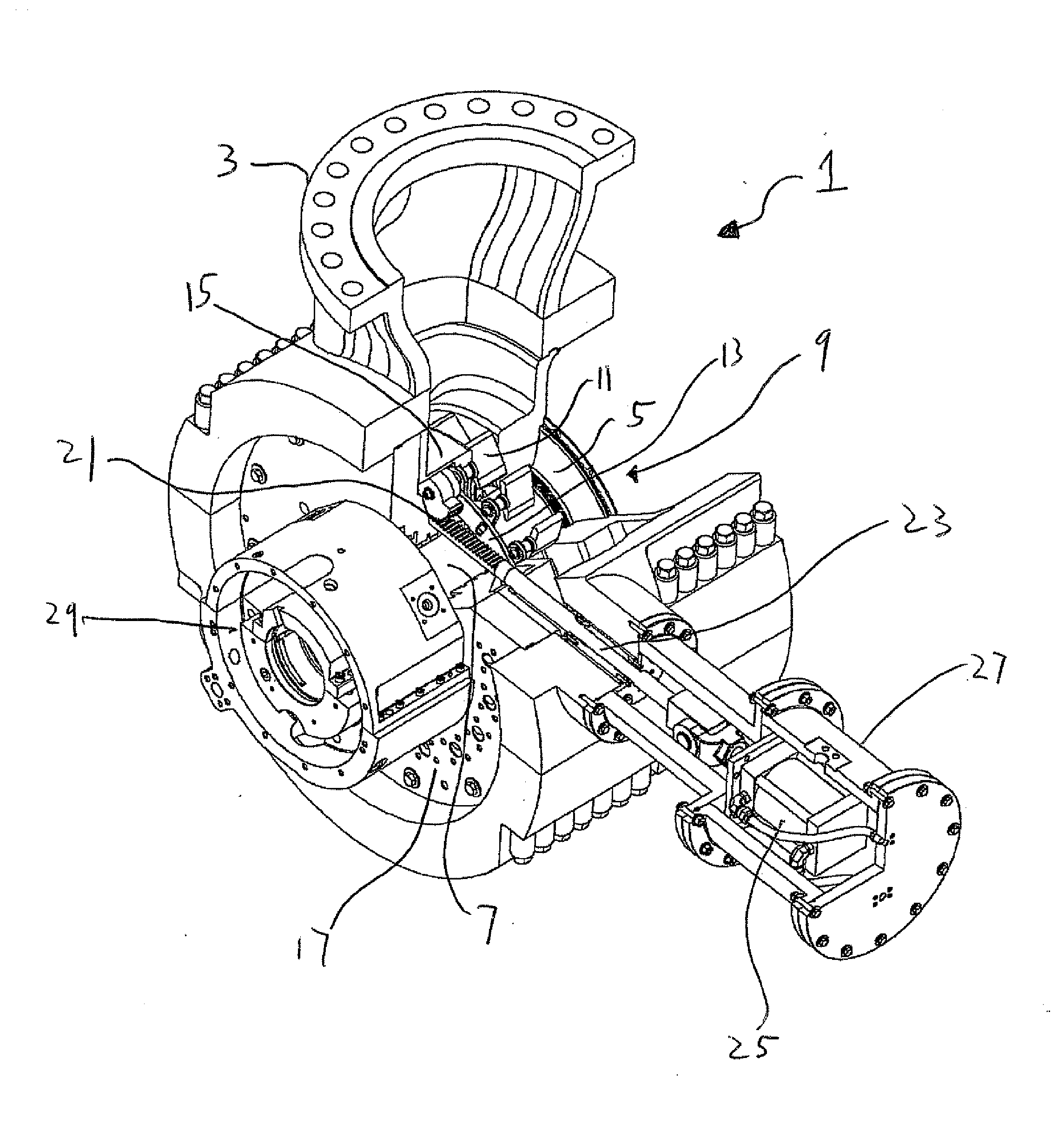
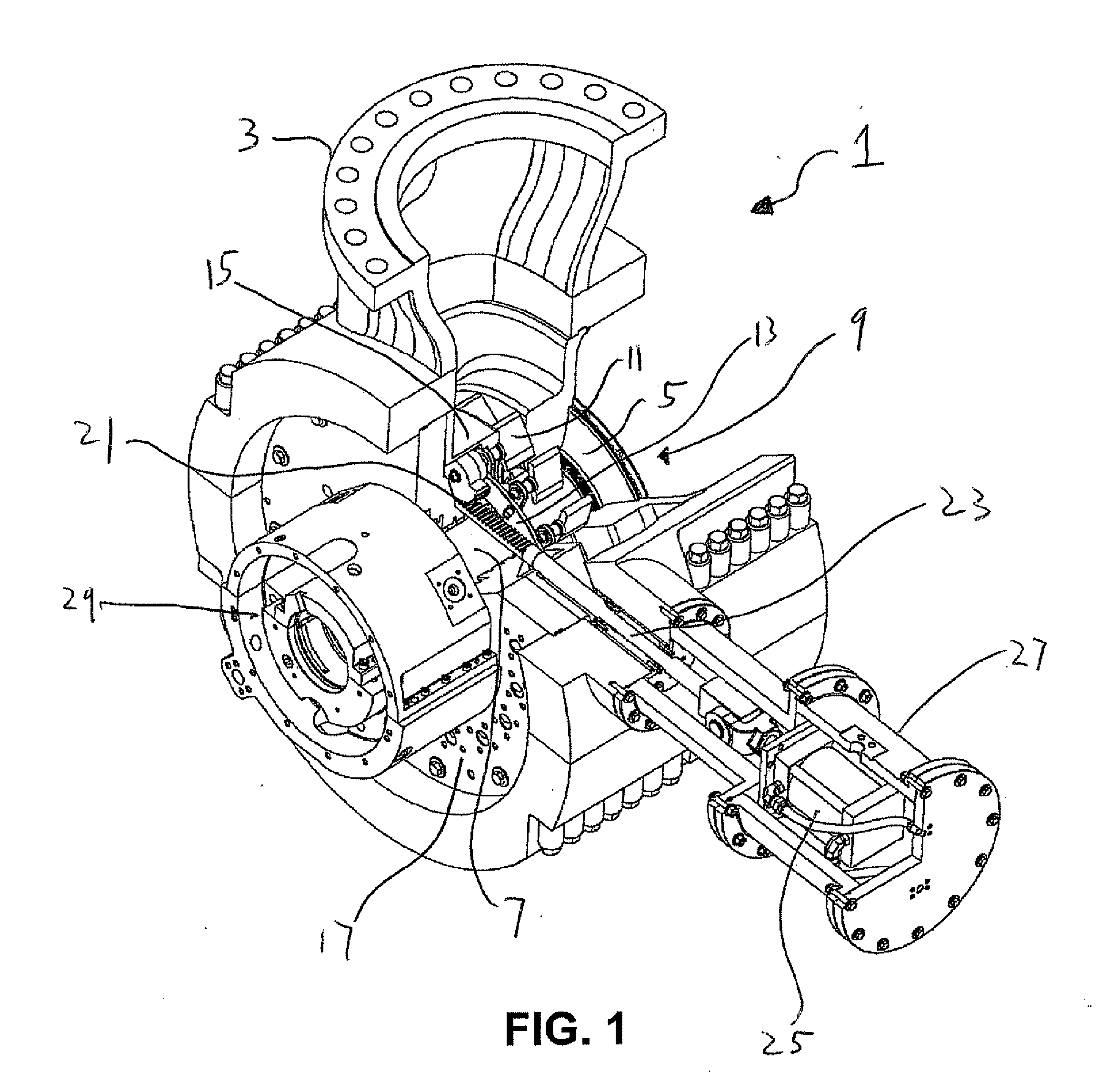
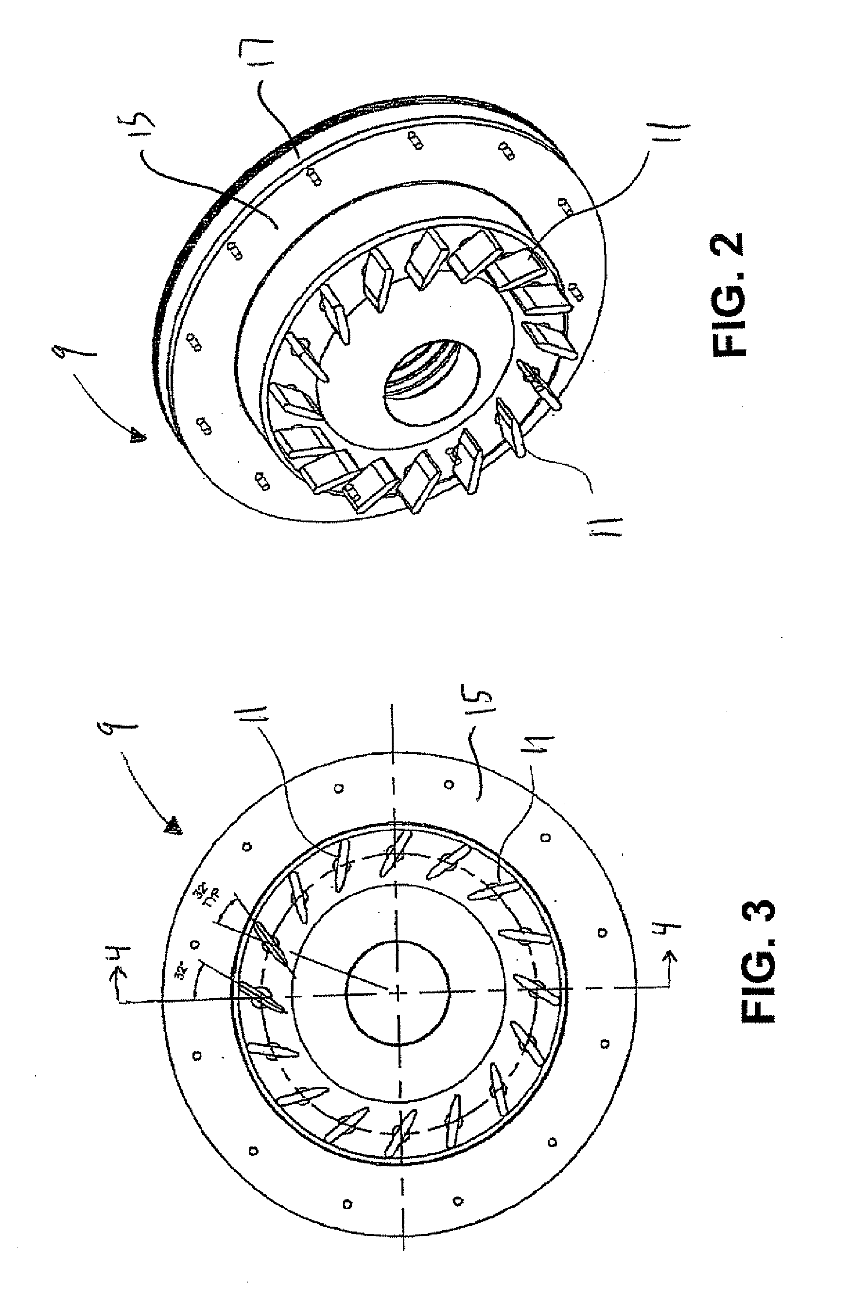
[0030]With reference to FIG. 1, a centrifugal compressor, denoted generally as reference numeral 1, includes a casing 3 with a rotor positioned therein. The rotor includes an impeller 5 and a shaft 7. An apparatus, or vane adjustment mechanism, denoted general...


PUM


Abstract

An apparatus for adjustment of inlet guide vanes of a compressor includes a ring having a plurality of slots spaced around a circumference thereof; a plurality of lever arm assemblies each having a pin that includes a body with a first end and a second end and a lever arm extending perpendicularly from the second end of the body of the pin; a plurality of vanes each coupled to an end of one of the plurality of lever arms by a shaft; and a rack and pinion drive mechanism. The pin of each of the lever arm assemblies is configured to be positioned within each of the plurality of slots such that the first end of the pin extends into the slot. The rack and pinion drive mechanism includes a pinion coupled to the shaft of one of the plurality of vanes, thereby creating a drive vane; and a driven rack operationally coupled to the pinion. The drive vane is configured to rotate the ring via the rack and pinion drive mechanism, thereby adjusting an angular position of the plurality of vanes.

Description

CROSS REFERENCE TO RELATED APPLICATIONS[0001]This application claims the benefit of U.S. Provisional Patent Application No. 60 / 922,713 entitled “Centrifugal Compressor Having Adjustable Inlet Guide Vanes” filed Apr. 10, 2007, which is hereby incorporated by reference in its entirety.BACKGROUND OF THE INVENTION[0002]1. Field of the Invention[0003]The present invention relates to the field of compressors and, more particularly, to an apparatus for the adjustment of inlet guide vanes to the compressor.[0004]2. Description of Related Art[0005]Centrifugal compressors are commonly used in the liquefied natural gas industry. This application requires a large range of compressor performance characteristics due to the nature of the liquification process. In order to achieve all the variations of performance needed, it is common industry practice to use a compressor that is able to vary the angle of its vanes near the inlet stage. The ability to change the angle of the inlet vanes for various...

Claims


Application Information

Patent Timeline
Patent Type & Authority Applications(United States)
IPC IPC(8): F04D27/00
CPCF04D29/462F04D29/4213F05D2250/51
Inventor HODDER, BRADLEY R.
Owner ELLIOTT CO
Why Eureka
Try Eureka