System and Method for Remote Monitoring and Control of Field Device

a field device and remote monitoring technology, applied in the field of system and method for remote monitoring and control of field devices, can solve the problems of manual reset of field device settings, increased labor intensity, and increased labor intensity,

Inactive Publication Date: 2010-07-08
INVENSYS SYST INC
View PDF15 Cites 22 Cited by
  • Summary
  • Abstract
  • Description
  • Claims
  • Application Information

AI Technical Summary

Benefits of technology

[0010]In another aspect of the invention, a system for remotely monitoring a field device includes a console communicably coupled to a field device located remotely therefrom. The console is configured to capture output data from an output buffer of one or more field devices, in which the output buffer is also configured to supply said output data to a field device user interface. The console is also configured to display a representation of the field device user interface, and to display the captured output data on the representation in substantially the same manner as displayed on the field device user interface.

Problems solved by technology

A field device may also transmit error conditions and alarms to the control station.
Otherwise, the person in the control station may have to attempt to interpret data to determine what the configuration settings look like, which tends to be awkward and counterintuitive.
A drawback to using a control station to run diagnostics is that the settings on the field device may have to be manually reset, i.e., at the site of the field device, requiring travel to the remote transmitter location.
These drawbacks tend to be exacerbated for relatively large, distributed networks in which field devices may be located as far away as a mile or more from the control station.
In these situations, an undesirably large investment of time and resources would be required to travel to each of the remote field devices to check configuration settings or to adequately respond to an alarm.

Method used


Image

  • System and Method for Remote Monitoring and Control of Field Device
  • System and Method for Remote Monitoring and Control of Field Device
  • System and Method for Remote Monitoring and Control of Field Device

Examples


Embodiment Construction

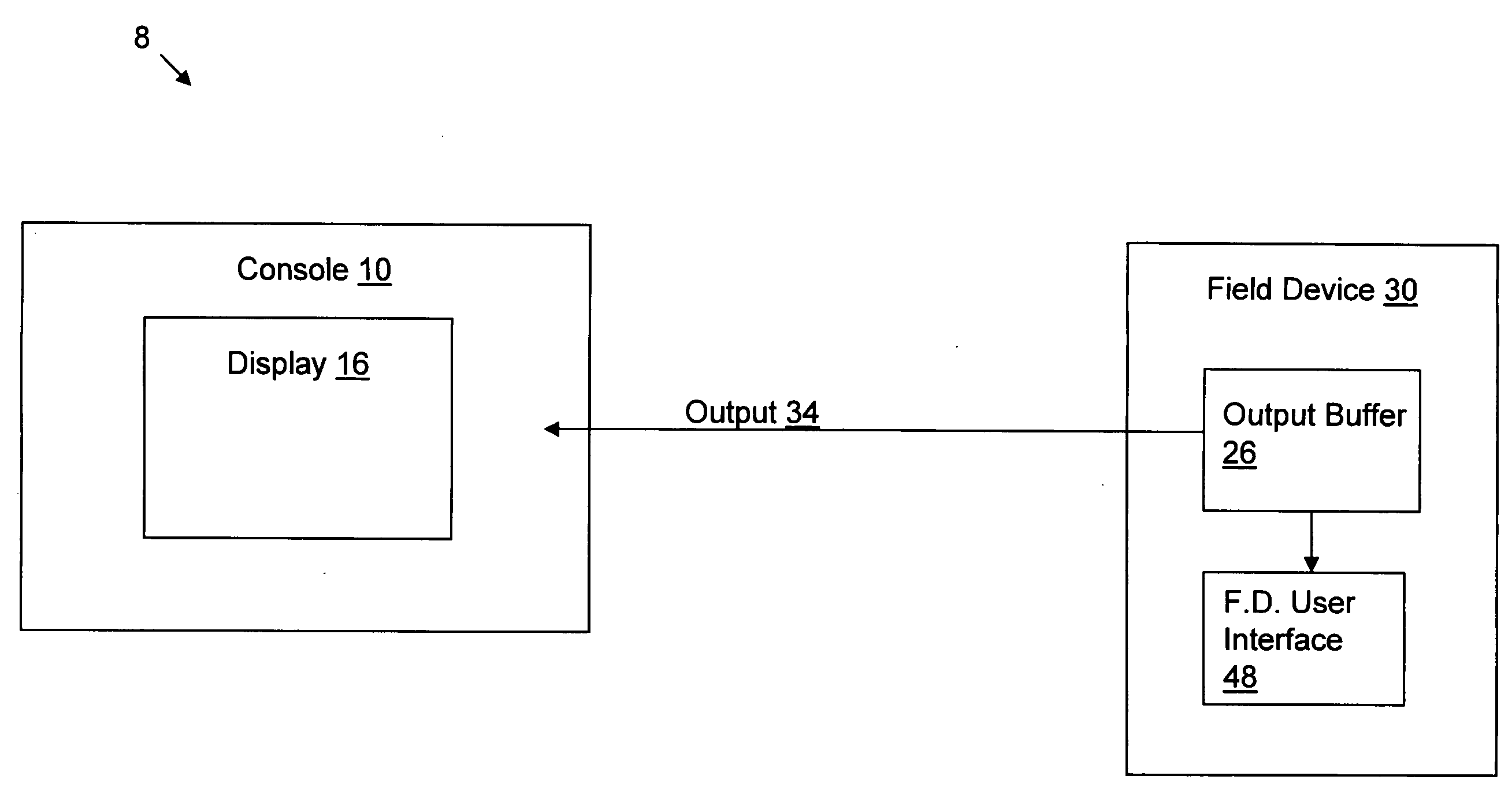
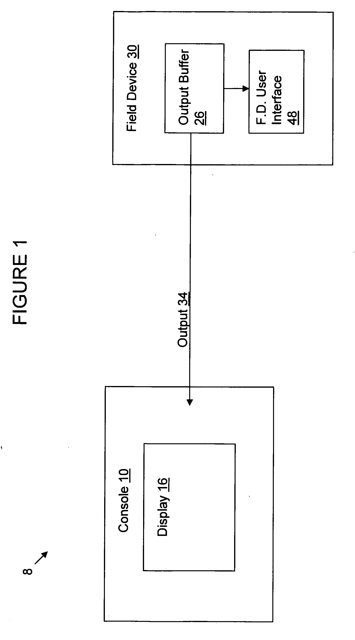
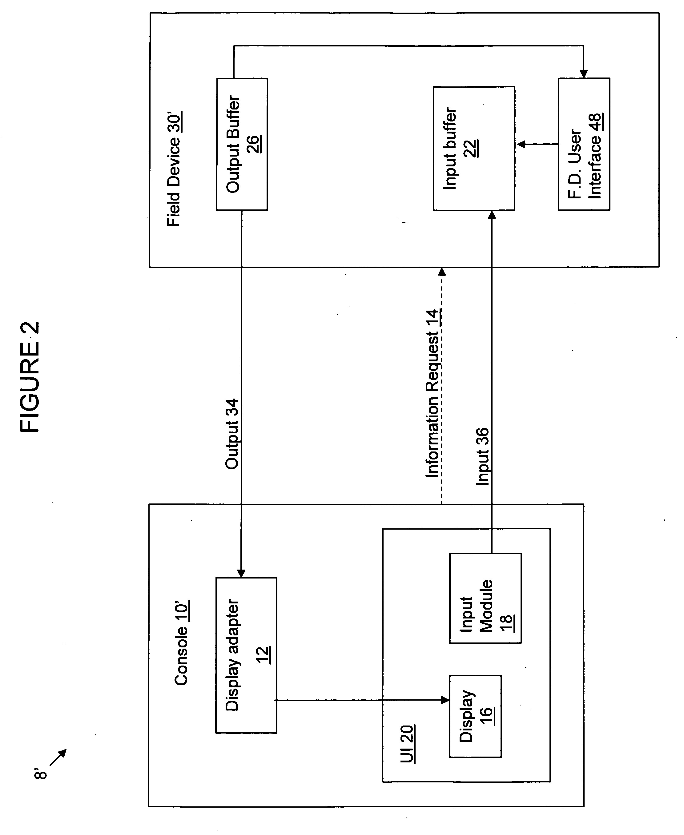
[0020]In the following detailed description, reference is made to the accompanying drawings that form a part hereof, and in which is shown by way of illustration, specific embodiments in which the invention may be practiced. These embodiments are described in sufficient detail to enable those skilled in the art to practice the invention, and it is to be understood that other embodiments may be utilized. It is also to be understood that structural, procedural and system changes may be made without departing from the spirit and scope of the present invention. The following detailed description is, therefore, not to be taken in a limiting sense, and the scope of the present invention is defined by the appended claims and their equivalents. For clarity of exposition, like features shown in the accompanying drawings shall be indicated with like reference numerals and similar features as shown in alternate embodiments in the drawings shall be indicated with similar reference numerals.

[002...


PUM


Abstract

A system and method for remotely monitoring a field device includes a console communicably coupled to a field device located remotely therefrom. The console is configured to capture output data from an output buffer of one or more field devices, in which the output buffer is also configured to supply said output data to a field device user interface. The console displays a representation of the field device user interface, and displays the captured output data on the representation in substantially the same manner as displayed on the field device user interface.

Description

BACKGROUND[0001]1. Technical Field[0002]This invention relates to field device monitoring and control, and more particularly to a remote virtual representation of a field device output, and remote control of the field device.[0003]2. Background Information[0004]Industrial control networks typically include field devices which control local operations such as gathering data from sensor systems, and monitoring the local site for error conditions. A field device may also transmit error conditions and alarms to the control station.[0005]In some networks, field devices may be configured from control stations. Configuration options include how the display looks, which measurement to display, and the number of decimal places of the displayed measurement. However, in order to determine whether the configurations have been appropriately implemented on the field devices, it is typically necessary to physically check the field device user interface, such as the front panel display. If the fiel...

Claims


Application Information

Patent Timeline
Patent Type & Authority Applications(United States)
IPC IPC(8): G06F3/048
CPCG05B19/0428G05B19/409G05B2219/24048G05B2219/24058H04Q2209/30G06F9/4445H04Q9/00H04Q2209/43H04Q2209/75G05B2219/24067G06F9/452
Inventor ALLSTROM, PETER E.FERREIRA, DAVID A.
Owner INVENSYS SYST INC
Why Eureka
Try Eureka