3D shutter glasses with mode switching based on orientation to display device

a technology of orientation and display device, applied in the field of systems, can solve the problem that different visual information cannot be provided to different players, and achieve the effect of less distraction

Active Publication Date: 2010-07-15
SONY COMPUTER ENTERTAINMENT INC
View PDF43 Cites 50 Cited by
  • Summary
  • Abstract
  • Description
  • Claims
  • Application Information

AI Technical Summary

Benefits of technology

[0012]The present invention can apply to solve the issue of two-player split screen game where traditional screens are divided in two portions and players sit side-by-side and play a game watching one screen with both player perspectives each occupying one half of the screen. The present invention can be configured to enable both players to see the full screen dimension of their game perspective. It also provides for less distraction as the present invention avoids the need for one player to see the other player's perspective on screen. Therefore, according to another aspect of the invention, a video game is provided to at least two players using a common display. The display is controlled to alternately display a full-screen image according to a first perspective of a video game and a full-screen image according to a second perspective of the video game. A first pair of LCD shutter glasses is synchronized to the display such that a first player using the first pair of LCD shutter glasses can play the video game while viewing the video game from the first perspective only. A second pair of LCD shutter glasses is synchronized to the display such that a second player using the second pair of LCD shutter glasses can play the video game while viewing the video game from the second perspective only.

Problems solved by technology

As an example, all players of a given video game view the same images on the monitor, and as a result, different visual information cannot be provided to different players unless a more complex and more expensive type of display is used, such as a head mounted monitor.

Method used


Image

  • 3D shutter glasses with mode switching based on orientation to display device
  • 3D shutter glasses with mode switching based on orientation to display device
  • 3D shutter glasses with mode switching based on orientation to display device

Examples


Embodiment Construction

[0034]The present invention provides for the use of a single monitor to present respective video feeds to two or more viewers in a manner that allows each viewer to only see the images from the video feed intended for that viewer. The invention also allows each viewer to only hear the sounds associated with that video feed.

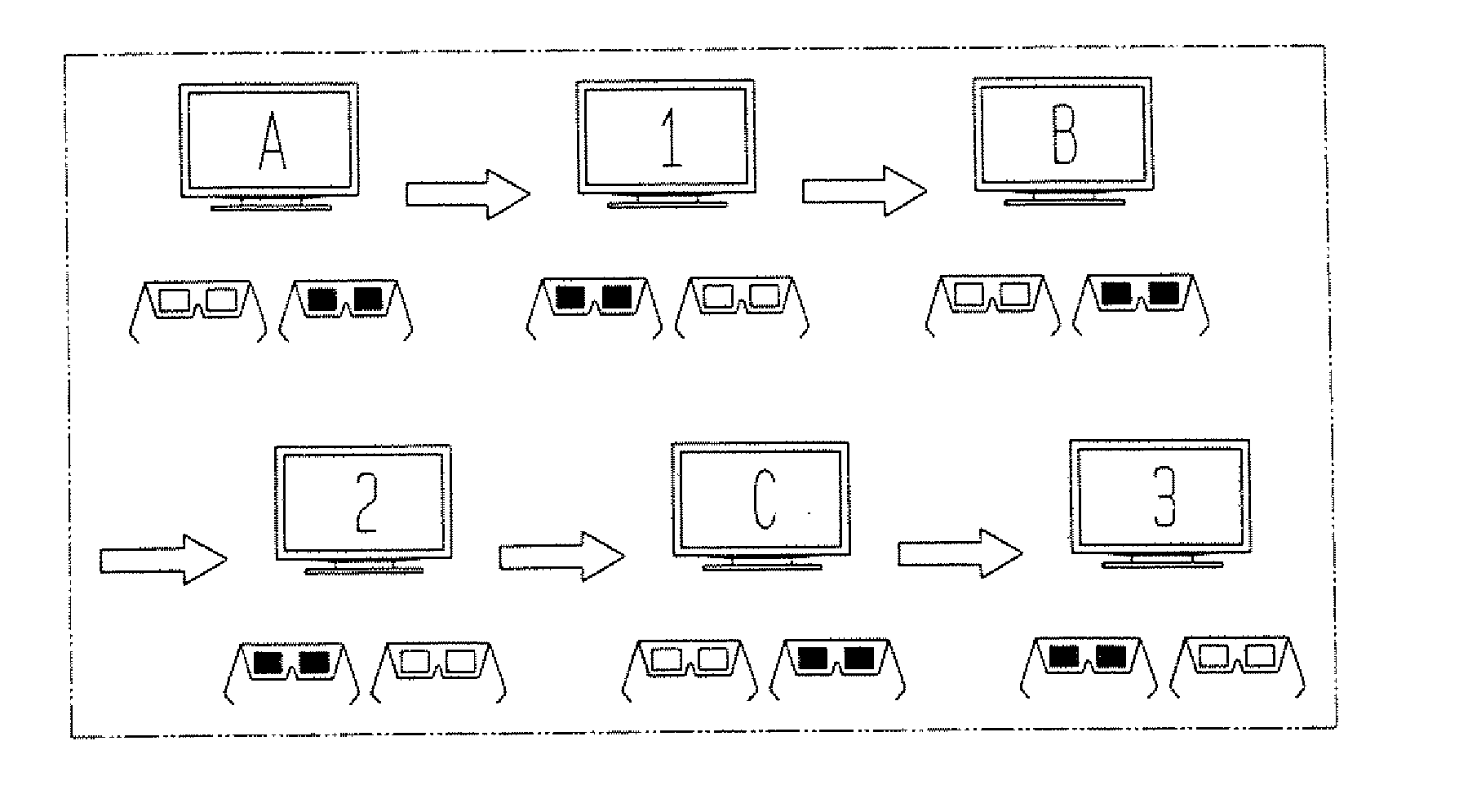
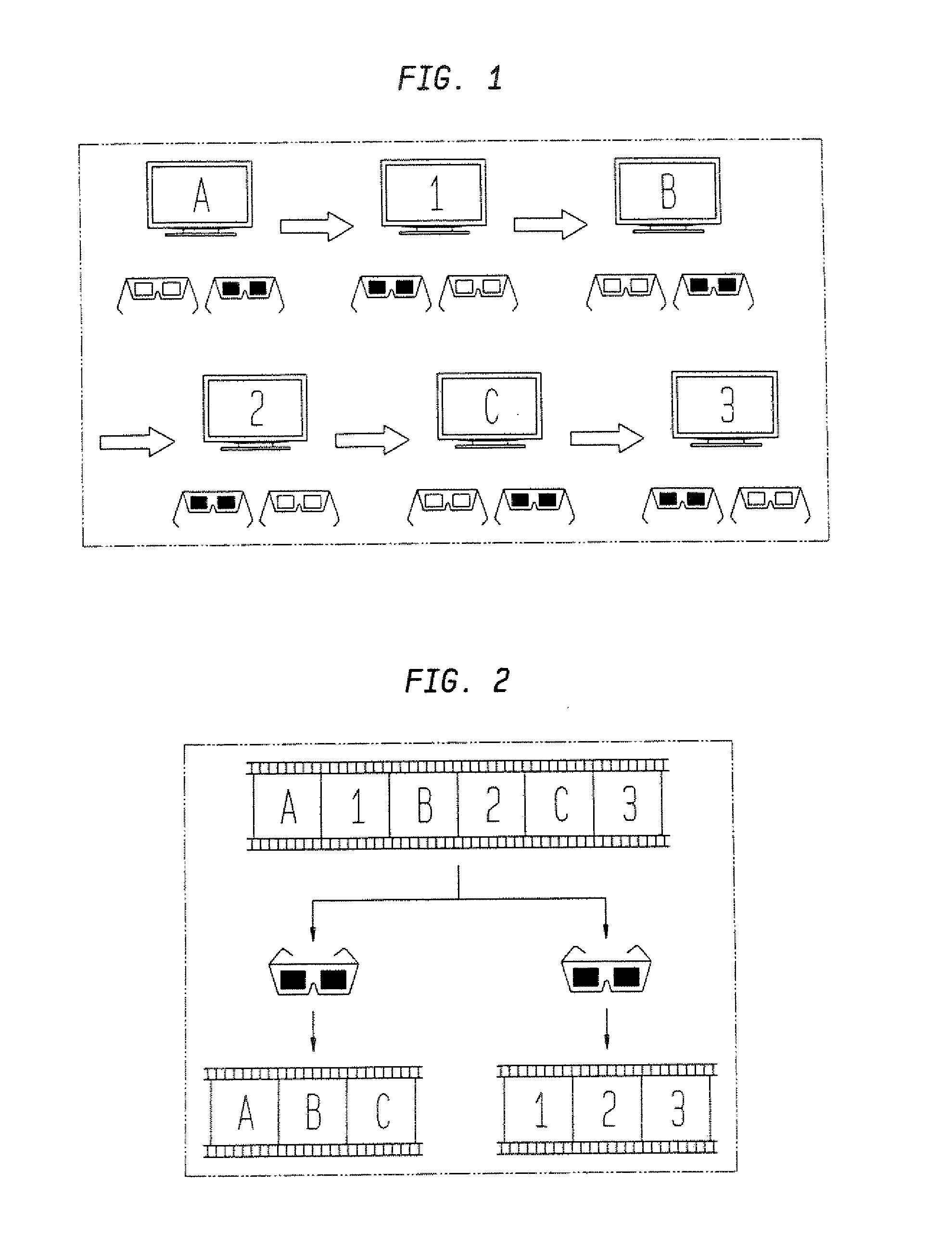
[0035]FIG. 1 illustrates an example of the invention in which a first video feed comprised of frames A, B, C, . . . and a second video feed comprised of frames 1, 2, 3, . . . are shown on the same monitor. The monitor alternately displays an image from each video feed, resulting in the displayed sequence of images A, 1, B, 2, C, 3, . . . shown in the upper portion of FIG. 2.

[0036]A first shuttered filter, such as the leftmost of the two pairs of LCD shutter glasses shown repeatedly in FIG. 1, is synchronized to the frames of first video feed. The first shuttered filter is open when the frames of the first video feed are shown on the monitor and is shuttered when t...


PUM


Abstract

A shuttered filter apparatus comprises a frame, one or more shuttered filters attached to the frame, and a tracker attached to the frame. Each shuttered filter is configured to selectively prevent a viewer from seeing through the filter in response to a signal from a controller. The tracker is configured to sense an orientation of the one or more shuttered filters relative to a video screen. The controller may use a signal from the tracker indicative of an orientation of the shutter filter(s) relative to enable shuttering when the shuttered filter apparatus is facing toward the video screen and disable shuttering when the shuttered filter apparatus is facing away from the video screen.

Description

CROSS-REFERENCE TO RELATED APPLICATIONS[0001]This application claims the benefit of the filing date of U.S. Provisional Patent Application No. 60 / 788,663 filed Apr. 3, 2006, the disclosure of which is hereby incorporated herein by reference.[0002]This application is a continuation of U.S. patent application Ser. No. 11 / 732,830 filed Apr. 3, 2007, the disclosure of which is hereby incorporated herein by reference, which claims the benefit of the filing date of U.S. Provisional Patent Application No. 60 / 788,663 filed Apr. 3, 2006, the disclosure of which is hereby incorporated herein by reference.[0003]This application is related to commonly-assigned, co-pending application number ______, entitled STEREOSCOPIC SCREEN SHARING METHOD AND APPARATUS (Attorney Docket No.: SCEA05067US03), filed the same day as the present application, the entire disclosures of which are incorporated herein by reference.[0004]This application is related to commonly-assigned, co-pending application number ___...

Claims


Application Information

Patent Timeline
Patent Type & Authority Applications(United States)
IPC IPC(8): H04N13/04
CPCH04N13/0438H04N13/0452H04N13/045H04N13/341H04N13/356H04N13/354
Inventor KO, HEINRICH SHIHPAIK, JAE WONZALEWSKI, GARY
Owner SONY COMPUTER ENTERTAINMENT INC
Why Eureka
Try Eureka