Systems and methods for improved digital RF transport in distributed antenna systems

a distributed antenna and network infrastructure technology, applied in the field of distributed antenna systems, can solve the problem of waste of fiber bandwidth within the digital das

Active Publication Date: 2010-07-15
COMMSCOPE TECH LLC
View PDF16 Cites 89 Cited by
  • Summary
  • Abstract
  • Description
  • Claims
  • Application Information

AI Technical Summary

Problems solved by technology

One problem with the digital DAS occurs when radio signals of interest within the RF spectrum are separated by bandwidths containing no signals interest.
In that case, fiber bandwidth within the digital DAS is wasted because all of the digital samples need to be transported at a rate sufficient to cover the full range of frequencies, not just the portions containing signals of interest.

Method used


Image

  • Systems and methods for improved digital RF transport in distributed antenna systems
  • Systems and methods for improved digital RF transport in distributed antenna systems
  • Systems and methods for improved digital RF transport in distributed antenna systems

Examples


Embodiment Construction

[0017]Embodiments of the present invention address the problem of efficiently transporting multiple non-adjacent communications bands within the digital transport of a distributed antenna system. This is accomplished by segregating from a digitized RF spectrum a plurality of smaller spectral regions that include relevant signals of interest, and discarding information not within those spectral regions. This segregation further allows the spectral regions to be processed independently, and each independently re-sampled (at a sampling rate based on their respective bandwidths) so that they can be transmitted over a common serial transport link. Each spectral region is transmitted using a number of timeslots in the serial bit stream that is a function of their respective bandwidths rather than the bandwidth of the entire digitized RF spectrum.

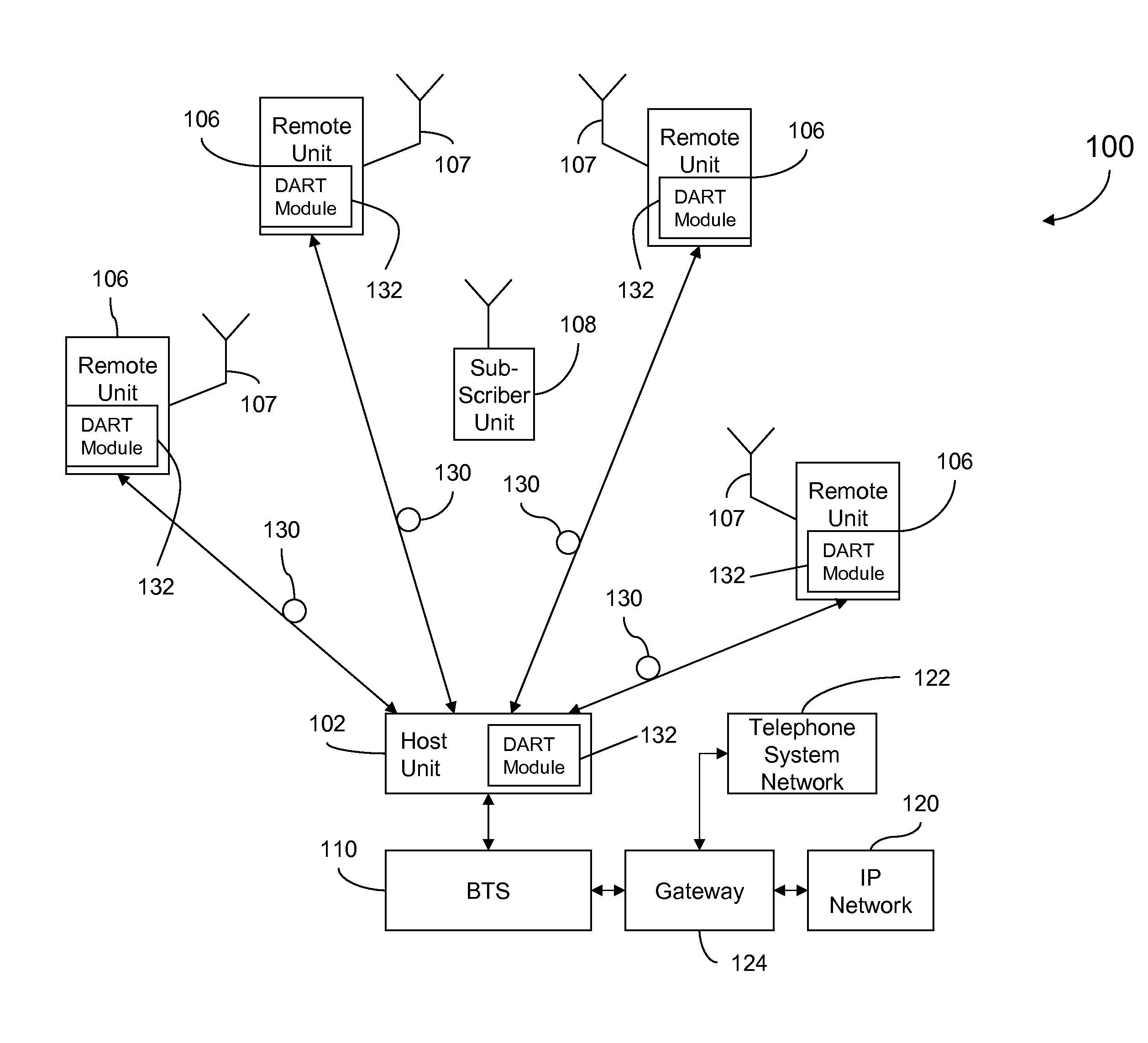
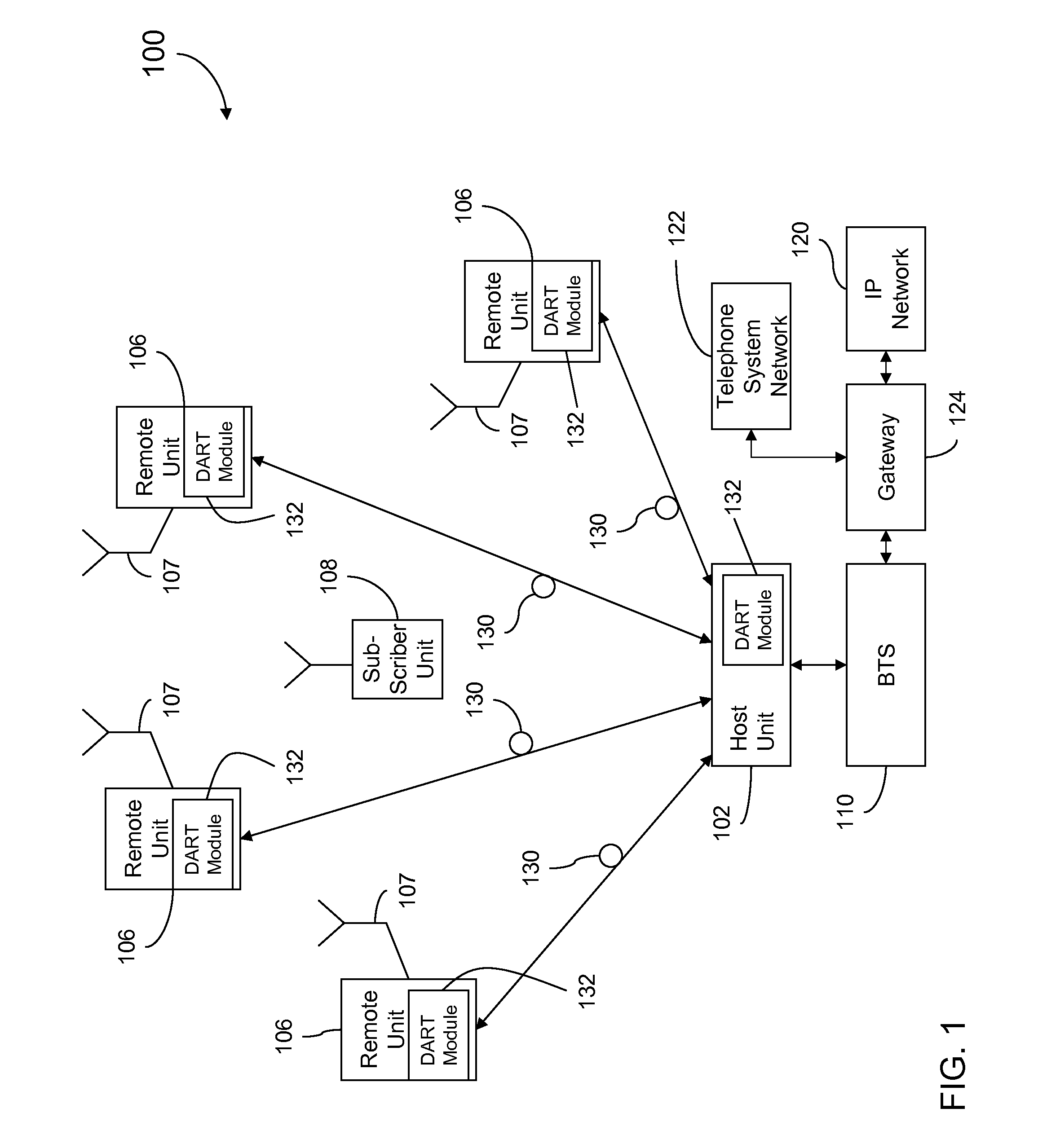
[0018]FIG. 1 is a block diagram of a distributed antenna system (DAS) 100 of one embodiment of the present invention for receiving and distributi...


PUM


Abstract

Systems and methods for improved digital RF transport in a DAS are provided. In one embodiment, a transceiver comprises: a receive path circuit including an RF reception interface coupled to an ADC, the ADC receiving a down-converted analog RF spectrum from the RF reception interface and producing a digitized RF spectrum at an input sampling rate; a logic device receiving the digitized RF spectrum and producing a first set of baseband data samples at a first sampling rate, corresponding to a first spectral region of the analog RF spectrum and a second set of baseband data samples at a second sampling rate, corresponding to a second spectral region of the analog RF spectrum. The logic device maps the first set and second sets of baseband data samples to a respective first set and second set of timeslots of a serial data stream transport frame.

Description

CROSS-REFERENCE TO RELATED APPLICATIONS[0001]This application claims the benefit of U.S. Provisional Application No. 61 / 144,349, filed on Jan. 13, 2009, which is incorporated herein by reference in its entirety.BACKGROUND[0002]A Distributed Antenna System (DAS) is a network of spatially separated antenna nodes connected to a common node via a transport medium that provides wireless service within a geographic area or structure. Common wireless communication system configurations employ a host unit as the common node, which is located at a centralized location (for example, at a facility that is controlled by a wireless service provider). The antenna nodes and related broadcasting and receiving equipment, located at a location that is remote from the host unit (for example, at a facility or site that is not controlled by the wireless service provider), are also referred to as “remote units.” Radio frequency (RF) signals are communicated between the host unit and one or more remote un...

Claims


Application Information

Patent Timeline
Patent Type & Authority Applications(United States)
IPC IPC(8): H04J3/00H04B1/38H04L27/00
CPCH04L27/0002H04L27/2338H04L27/144H04W88/085H04B1/0028H04B1/40H04B7/04
Inventor CANNON, JEFFREY J.ZAVADSKY, DEANWALA, PHILIP M.
Owner COMMSCOPE TECH LLC
Why Eureka
Try Eureka