
Image blur correction device and imaging apparatus equipped therewith

a technology of image blur correction and imaging apparatus, which is applied in the field of image blur correction devices and imaging apparatus equipped therewith, can solve the problems of adverse effects on image blur correction performance including camera shake correction, and increase in aberration or focal shift, so as to prevent deterioration of correction control performance and increase the consumption current of coils

Active Publication Date: 2010-07-15
RICOH KK
View PDF9 Cites 31 Cited by
  • Summary
  • Abstract
  • Description
  • Claims
  • Application Information

AI Technical Summary

Benefits of technology

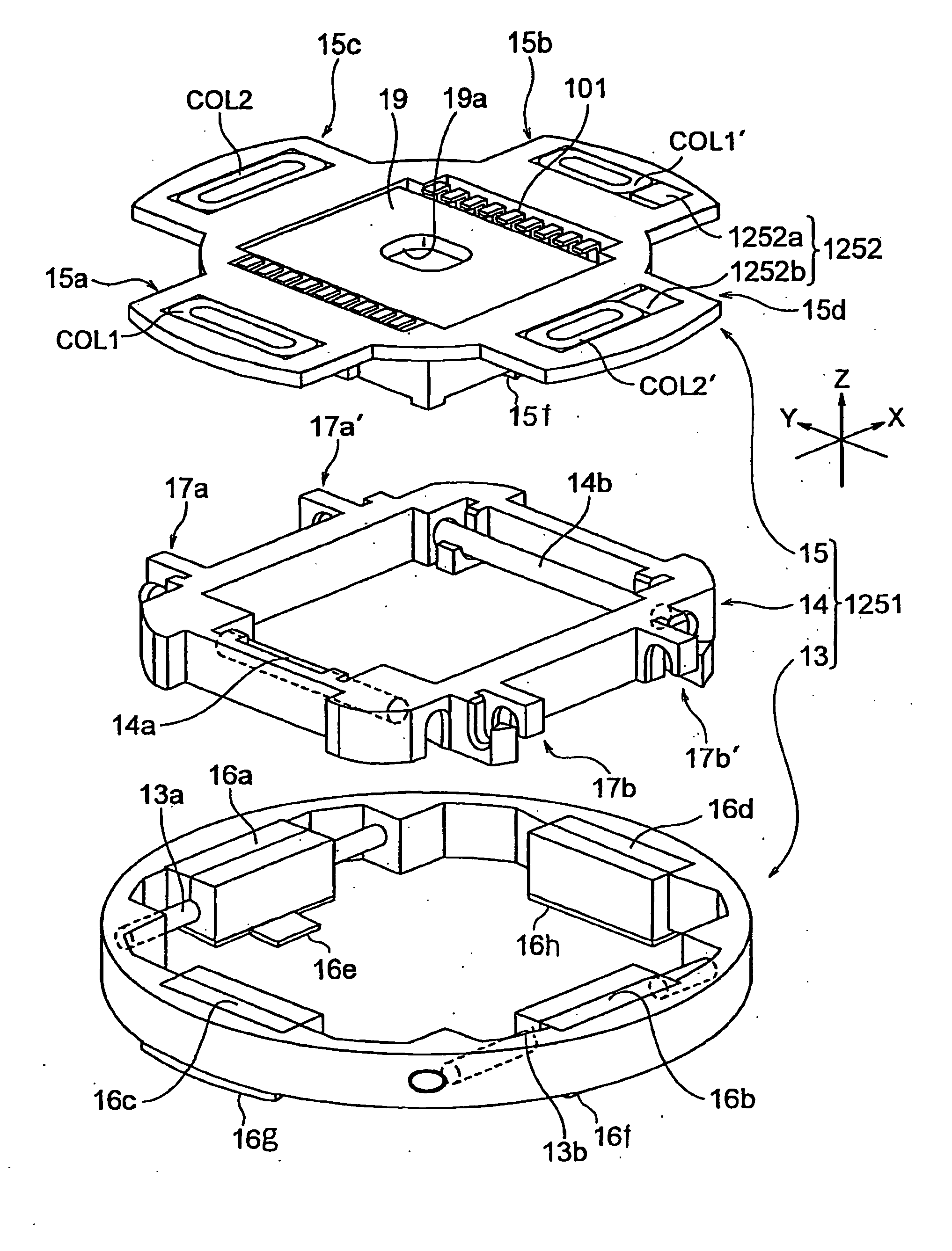
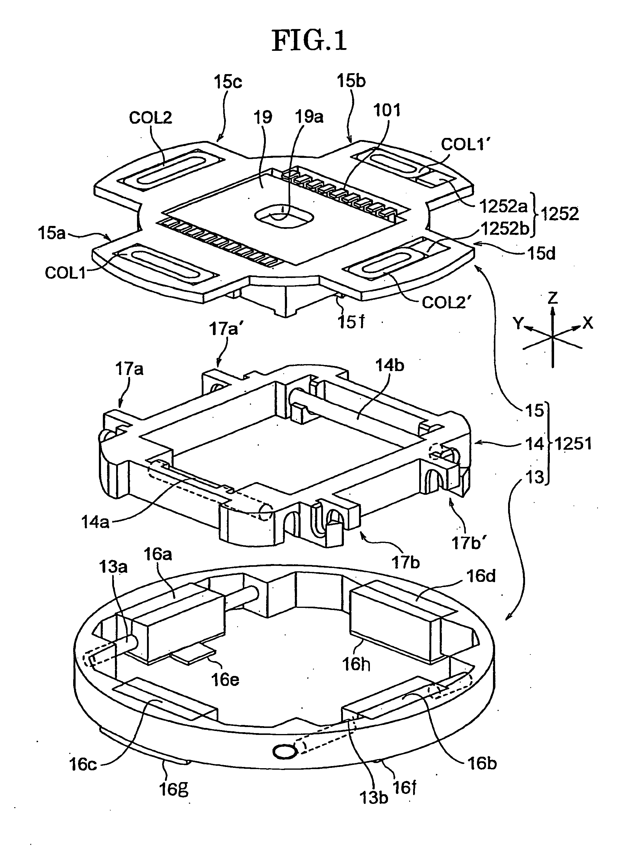
[0019]According to the present invention, the urging magnets (permanent magnets) are provided in the movable frame in addition to the drive mechanism which chives the movable frame, and loose-fitting between the guide part and the guide supporting part in movement of the movable frame is removed by use of the attractive force between the magnets and the magnetic bodies in the fixed frame. Thus, there is no influence on a magnetic field distribution to coils for driving, and there is no risk of causing lowering of driving force, an increase in a variation of the driving force within a moving range, generation of driving force in an unnecessary direction and the like.
[0020]Moreover, according to one aspect of the present invention, the combinations of the urging magnets and the magnetic bodies are provided on both sides of the lens or the imaging element. Thus, since no bias occurs in the urging force to the movable frame, the loose-fitting between the guide part and the guide supporting part in movement of the movable frame can be surely removed.
[0021]Moreover, according to one aspect of the present invention, the magnetic bodies are formed by extending the yokes in the voice coil motor as the drive mechanism. Thus, it is possible to impart a function of removing the loose-fitting between the guide part and the guide supporting part in movement of the movable frame without newly adding magnetic parts.
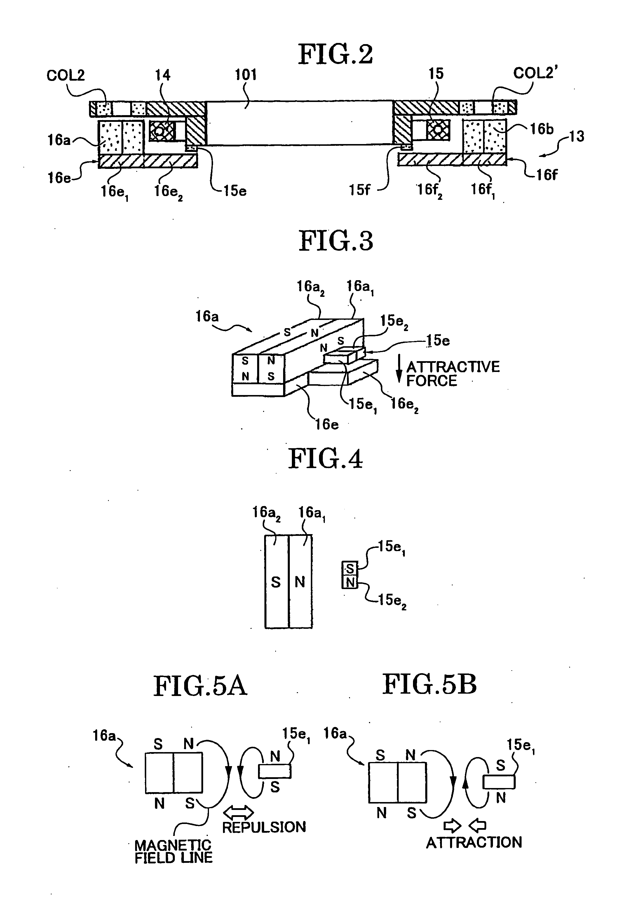
[0022]Moreover, according to one aspect of the present invention, as the urging magnets, a plurality of permanent magnets having different magnetization directions are arranged in parallel with the permanent magnets in the drive mechanism. Thus, magnetic force acting between the permanent magnets as driving magnets and the urging magnets can be eliminated. As a result, it is possible to prevent deterioration of correction control performance or an increase in consumption current of the coils due to addition of attractive or repulsive force to the force required for correction generated by driving coils. Specifically, the attractive or repulsive force is made to act on the permanent magnets as the driving magnets by the urging magnets.
[0023]According to the present invention, the urging magnets (permanent magnets) are provided in the first movable frame in addition to the drive mechanism which drives the first movable frame, and loose-fitting between the first guide part and the first guide supporting part in movement of the first movable frame is removed by use of the attractive force between the magnets and the magnetic bodies in the fixed frame. Thus, there is no influence on a magnetic field distribution to coils for driving, and there is no risk of causing lowering of driving force, an increase in a variation of the driving force within a moving range, generation of driving force in an unnecessary direction and the like. Moreover, since the configuration in which the first movable frame is urged toward the fixed frame is adopted, loose-fitting between the second guide part and the second guide supporting part in movement of the second movable frame can also be removed without adding new parts to the second movable frame.
[0024]According to the present invention, the imaging apparatus includes the image blur correction device which can perform normal driving while removing the loose-fitting in movement of the movable frames (the first and second movable frames). Thus, an image whose blur is properly corrected can be obtained.

Problems solved by technology

Meanwhile, in the imaging apparatus described above, if there is loose-fitting in guides of a movable mechanism such as a lens and the imaging element, in other words, if loose-fitting occurs between the guide stage and the Y movable frame due to a given amount of space in a spot where the guide stage holds the Y movable frame for smooth movement of the Y movable frame along the X-Y plane, the Y movable frame cannot be smoothly moved.
Thus, there is a problem that image blur correction performance including the camera shake correction described above is adversely affected.
Moreover, the imaging apparatus has a problem that the lens or the imaging element is inclined by the loose-fitting to cause an increase in aberration or a focal shift and thus imaging performance is also deteriorated.
As a result, there is a risk of causing lowering of driving force, an increase in a variation of the driving force within a moving range, generation of driving force in an unnecessary direction and the like in the drive mechanism.
Moreover, in the mechanism disclosed in Japanese Patent No. 3728094, force urging a supporting part that movably supports a movable frame is likely to get off balance.
Thus, removal of loose-fitting may not be surely performed.

Method used


Image

  • Image blur correction device and imaging apparatus equipped therewith
  • Image blur correction device and imaging apparatus equipped therewith
  • Image blur correction device and imaging apparatus equipped therewith

Examples


modified example

[0282]FIG. 36 is a circuit diagram showing a modified example of the feedback circuit 50. Here, the processor 104 controls driving of a coil driver MD4 by means of PWM control so as to control the power distribution to the coils COM″ and COL2″.

[0283]More particularly, a normal direction signal CON1 and a reverse direction signal CON2 are inputted to the coil driver MD4, and pulse voltages Vin1 and Vin2 are also inputted thereto. The power distribution voltages to the coils COL1″ and COL2″ are increased as the duration of a high level of the pulse signal gets longer.

(Details of Photographing by Turning on Camera Shake Correction Mechanism)

[0284]As shown in FIG. 37, when the camera shake correction switch SW14 is turned on (S.1), the gyro sensors S1B and S2A are powered on (S.2). When the release switch SW1 is pressed to complete half-pressing (S.3), an autofocus operation (focusing operation) is started (S.4). At the same time as the start of the autofocus operation, the mechanical f...


PUM


Abstract

An image blur correction device includes: a movable frame which is equipped with a lens or an imaging element and has a guide part; a fixed frame having a guide supporting part which movably supports the movable frame by coming into contact with the guide part; and a drive mechanism which drives the movable frame for correcting image blur by moving the movable frame relative to the fixed frame. The fixed frame has magnetic bodies, and the movable frame has urging magnets at positions corresponding to the magnetic bodies. Specifically, the urging magnets use attractive force between the magnets and the magnetic bodies, so as to urge the movable frame in a direction in which the guide part and the guide supporting part come into contact with each other.

Description

PRIORITY CLAIM[0001]The present application is based on and claims priority benefit from each of Japanease Patent Application Nos. 2006-226290, filed on Aug. 23, 2006 and 2006-226291, filed on Aug. 23, 2006, the disclosure of which is incorporated herein by reference in its entirety.TECHNICAL FIELD[0002]The present invention relates to an image blur correction device which corrects image blur when a subject image is photographed by allowing the subject image to image on an imaging element which generates image data to form the subject image, and also relates to an imaging apparatus. More particularly, the present invention relates to an image blur correction device having an image blur correction function which enables the photographing of a subject image whose blur is corrected by allowing an imaging element to follow movement of the subject image due to camera shake, and also relates to an imaging apparatus equipped with the image blur correction device.BACKGROUND ART[0003]There h...

Claims


Application Information

Patent Timeline
Patent Type & Authority Applications(United States)
IPC IPC(8): G03B17/00
CPCG03B5/00H04N5/2253G03B2205/0038G03B2205/0069H04N5/23248H04N23/54H04N23/68
Inventor OHNO, TAKEHIDE
Owner RICOH KK
Learn More