
Quick clamping assembly for driving a knockout punch

a technology of quick clamping and knockout punch, which is applied in the direction of metal working equipment, metal-working equipment, manufacturing tools, etc., can solve the problems of user frustration, 60 seconds to accomplish, and frustrating and inefficient users

Inactive Publication Date: 2010-07-22
TEXTRON INNOVATIONS
View PDF23 Cites 20 Cited by
  • Summary
  • Abstract
  • Description
  • Claims
  • Application Information

AI Technical Summary

Problems solved by technology

Overall, this device works well, however, the most time consuming task is screwing the knockout punch onto the draw stud, which can take as long as thirty to sixty seconds to accomplish depending on the length of the draw stud.
Of course, this can be frustrating and inefficient for the user, especially when a great number of holes need to be punched.
This, in turn, makes it difficult for the user to slide the device 20 off of the draw stud 22, resulting in user frustration.
However in practice, this device 20 has too many parts which make assembly difficult.
Likewise, it is difficult to hold all six springs 44, 48 in place when assembling the device 20.
In addition, the great number of components, especially springs 44, 48, adds unwanted cost to the device 20.
This makes the device 20 inconvenient for use with many prior art draw studs, which also adds cost to the overall assembly.

Method used


Image

  • Quick clamping assembly for driving a knockout punch
  • Quick clamping assembly for driving a knockout punch
  • Quick clamping assembly for driving a knockout punch

Examples


Embodiment Construction

[0034]While the invention may be susceptible to embodiment in different forms, there is shown in the drawings, and herein will be described in detail, a specific embodiment with the understanding that the present disclosure is to be considered an exemplification of the principles of the invention, and is not intended to limit the invention to that as illustrated and described herein.

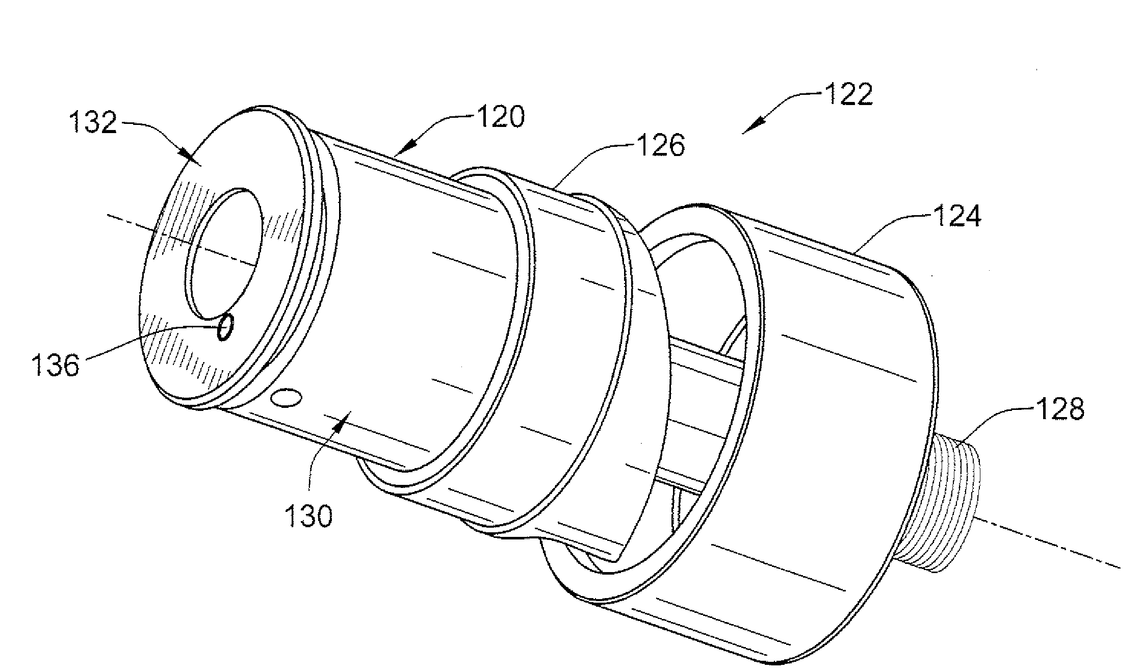
[0035]FIGS. 5 and 6 show a preferred embodiment of a clamping device 120 for driving a knockout punch 122 in accordance with the present invention. The knockout punch 122 is standard and includes a die 124, a punch 126 and a standard draw stud 128, each of which is readily available in the field, and therefore, are not described herein.

[0036]The clamping device 120 includes an outer member 130, an inner member 132, wedges 134 that are trapped in between the outer and inner members 130, 132, and a pin 136 and a ball 138 for locking the outer and inner member 130, 132 together. The pin 136 may take the for...


PUM

PropertyMeasurementUnit
Lengthaaaaaaaaaa
Sizeaaaaaaaaaa

Abstract

A clamping assembly for driving a knockout punch is provided. The clamping assembly has an outer member, an inner member, and wedges that are guided by keyways on the inner member. A user pushes onto the inner member, which causes the wedges to contact a cam surface on the outer member, which forces the wedges in a radial inward direction until threads provided on said wedges clamp onto complimentary shaped threads on a draw stud.

Description

FIELD OF THE INVENTION[0001]This invention is generally directed to a clamping assembly for use with a knockout punch.BACKGROUND OF THE INVENTION[0002]Knockout punches are used routinely to create holes in thin layers of material such as the sheet metal found on electrical boxes. Knockout punches are used in conjunction with a draw stud, a ram, and a die which are all used to punch a hole.[0003]The user drills a pilot hole approximately in the center of the area where the final hole needs to be located. The draw stud, which has been attached to the ram, has the die slid over its free end until the die abuts the ram. The draw stud is then inserted with its free end first through the pilot hole until the die is seated against on one side of a sheet of material. The knockout punch, which has a central hole with internal threads, is screwed onto the free end of the draw stud which has complimentary-shaped external threads on it. This process continues until the knockout punch impinges o...

Claims


Application Information

Patent Timeline
IPC IPC(8): B26F1/14B26F1/00
CPCB21D28/343Y10T83/9428
Inventor NORDLIN, WILLIAM F.
Owner TEXTRON INNOVATIONS
Features
  • Generate Ideas
  • Intellectual Property
  • Life Sciences
  • Materials
  • Tech Scout
  • Unparalleled Data Quality
  • Higher Quality Content
  • 60% Fewer Hallucinations
Learn More