
Catch and snare system for an unmanned aerial vehicle

a technology for aerial vehicles and traps, applied in emergency apparatuses, transportation and packaging, weapons, etc., can solve the problems of ineffective previous intercept systems, negative effect on flying properties, and debris field, and achieve the effect of preventing chemical releas

Inactive Publication Date: 2010-07-22
HONEYWELL INT INC
View PDF46 Cites 83 Cited by
  • Summary
  • Abstract
  • Description
  • Claims
  • Application Information

AI Technical Summary

Benefits of technology

[0003]The discovery presented herein details a catch and snare system for an unmanned aerial vehicle that has a beneficial effect of preventing the release of chemical or biological agents from the captured unmanned aerial vehicle into the environment.
[0004]Thus, in one aspect, the present invention provides a catch and snare system for an unmanned aerial vehicle comprising: (a) a detection system, (b) a deployment system in communication with the detection system, (c) a capture system placed at an interference position by the deployment system, wherein the capture system comprises a net, a plurality of foam deploying canisters attached to the net for deploying foam, and at least one canister for deploying a decelerating parachute attached to the net, wherein the foam prevents the release of chemical or biological agents from the captured unmanned aerial vehicle into the environment, and (d) a descent system to bring the capture system and a captured unmanned aerial vehicle back to earth.
[0005]In a second aspect, the present invention provides a catch and snare system for an unmanned aerial vehicle comprising: (a) a detection system, (b) a deployment system in communication with the detection system, (c) a capture system placed at an interference position by the deployment system, wherein the capture system comprises a plurality of foam mines that create an aerial minefield that is triggered to expand just before the unmanned aerial vehicle flies into the minefield to adhere to the unmanned aerial vehicle via surface contact with the foam while the plurality of foam mines continue to expand until at least a portion of the unmanned aerial vehicle is encapsulated in the expanded foam mines, wherein the foam prevents the release of chemical or biological agents from the captured unmanned aerial vehicle into the environment, and (d) a descent system to bring the capture system and a captured unmanned aerial vehicle back to earth.
[0006]In a third aspect, the present invention provides a method for employing a catch and snare system for an unmanned aerial vehicle comprising: (a) monitoring the perimeter of a target site, (b) detecting an unmanned aerial vehicle within a predetermined distance of the perimeter, (c) launching a capture system, (d) capturing the unmanned aerial vehicle, wherein capturing the unmanned aerial vehicle comprises the steps of (i) deploying a net, (ii) deploying at least one decelerating parachute, (iii) deploying foam, (iv) blocking the unmanned aerial vehicle's flight path and causing the unmanned aerial vehicle to contact the net, and (v) encapsulating at least a portion of the unmanned aerial vehicle in the foam and the net, wherein the foam prevents the release of chemical or biological agents from the captured unmanned aerial vehicle into the environment, and (e) guiding the captured unmanned aerial vehicle to earth.
[0007]In a fourth aspect, the present invention provides a method for employing a catch and snare system for an unmanned aerial vehicle comprising: (a) monitoring the perimeter of a target site, (b) detecting an unmanned aerial vehicle within a predetermined distance of the perimeter, (c) launching a capture system, (d) capturing the unmanned aerial vehicle, wherein the step of capturing the unmanned aerial vehicle comprises the steps of (i) dispersing a plurality of foam mines to create an aerial minefield, (ii) triggering the plurality of foam mines to expand just before the unmanned aerial vehicle flies into the minefield, (iii) adhering the plurality of foam mines to the unmanned aerial vehicle via surface contact with the foam while the plurality of foam mines continue to expand, and (iv) encapsulating at least a portion of the unmanned aerial vehicle in the expanded foam mines, wherein the foam prevents the release of chemical or biological agents from the captured unmanned aerial vehicle into the environment, and (e) guiding the captured unmanned aerial vehicle to earth.

Problems solved by technology

One example of an interception system operates by deploying a kill missile to destroy the incoming missile, which results in a debris field.
Still further, an intercept device for flying objects exists that neither seriously damages nor destroys the flying object in question, but has a negative effect on its flying properties and then the intercept device destroys itself at a selected point in time so the flying object can return to its airfield unhindered and safely land.
However, with the advent of the low cost unmanned aerial vehicle, which can carry a significant payload of biological or chemical weapons, these previous interception systems are ineffective.
In addition, simply capturing the UAV in a net or containment blanket will not prevent the chemical or biological agent from leeching out into the atmosphere since these structures are not equipped to contain vapors and / or liquids.

Method used


Image

  • Catch and snare system for an unmanned aerial vehicle
  • Catch and snare system for an unmanned aerial vehicle
  • Catch and snare system for an unmanned aerial vehicle

Examples


Embodiment Construction

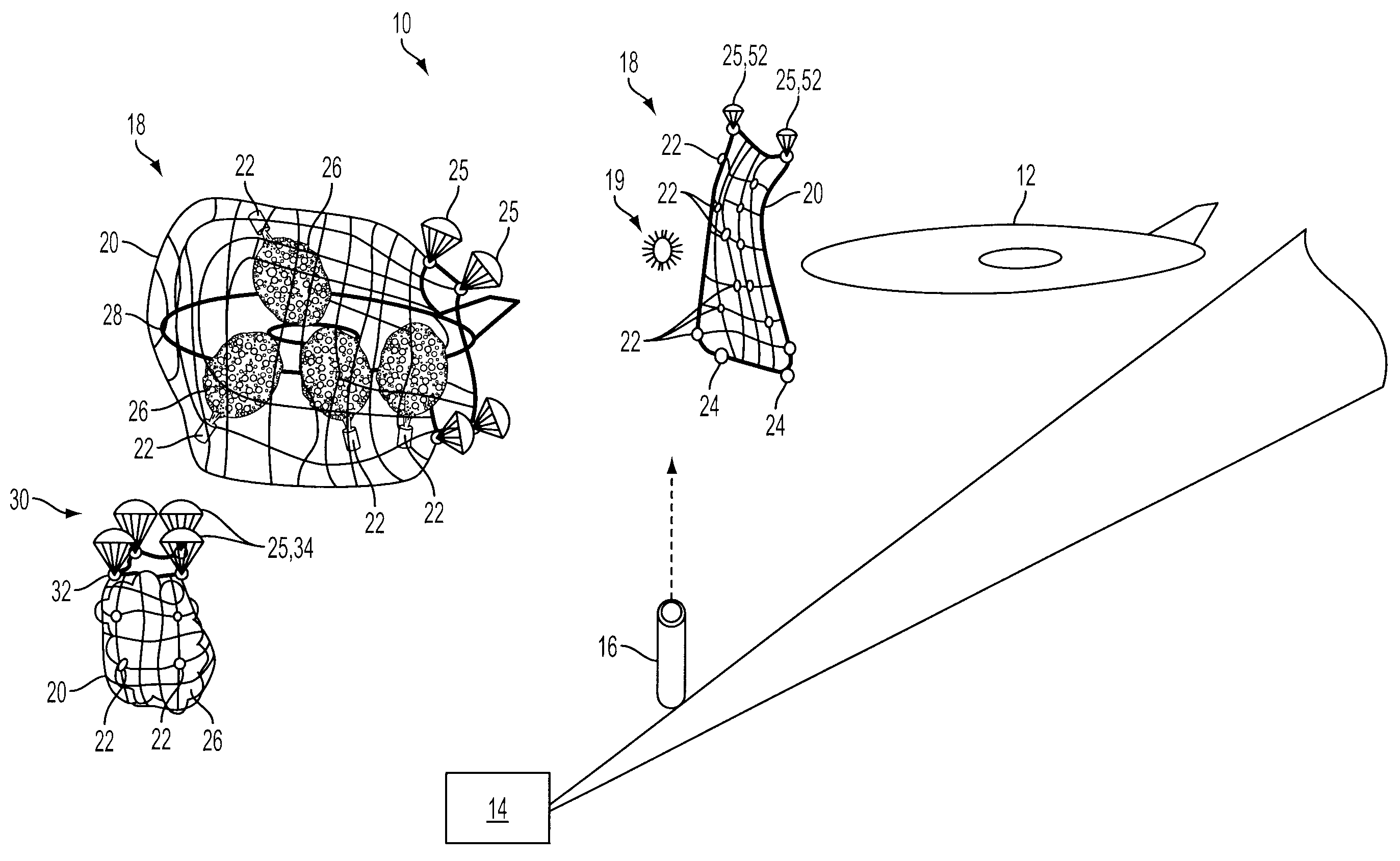
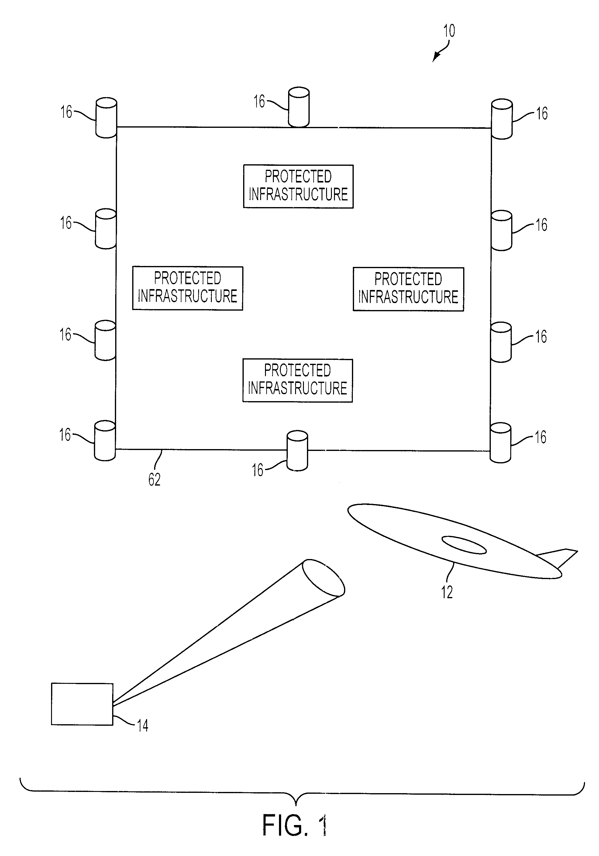
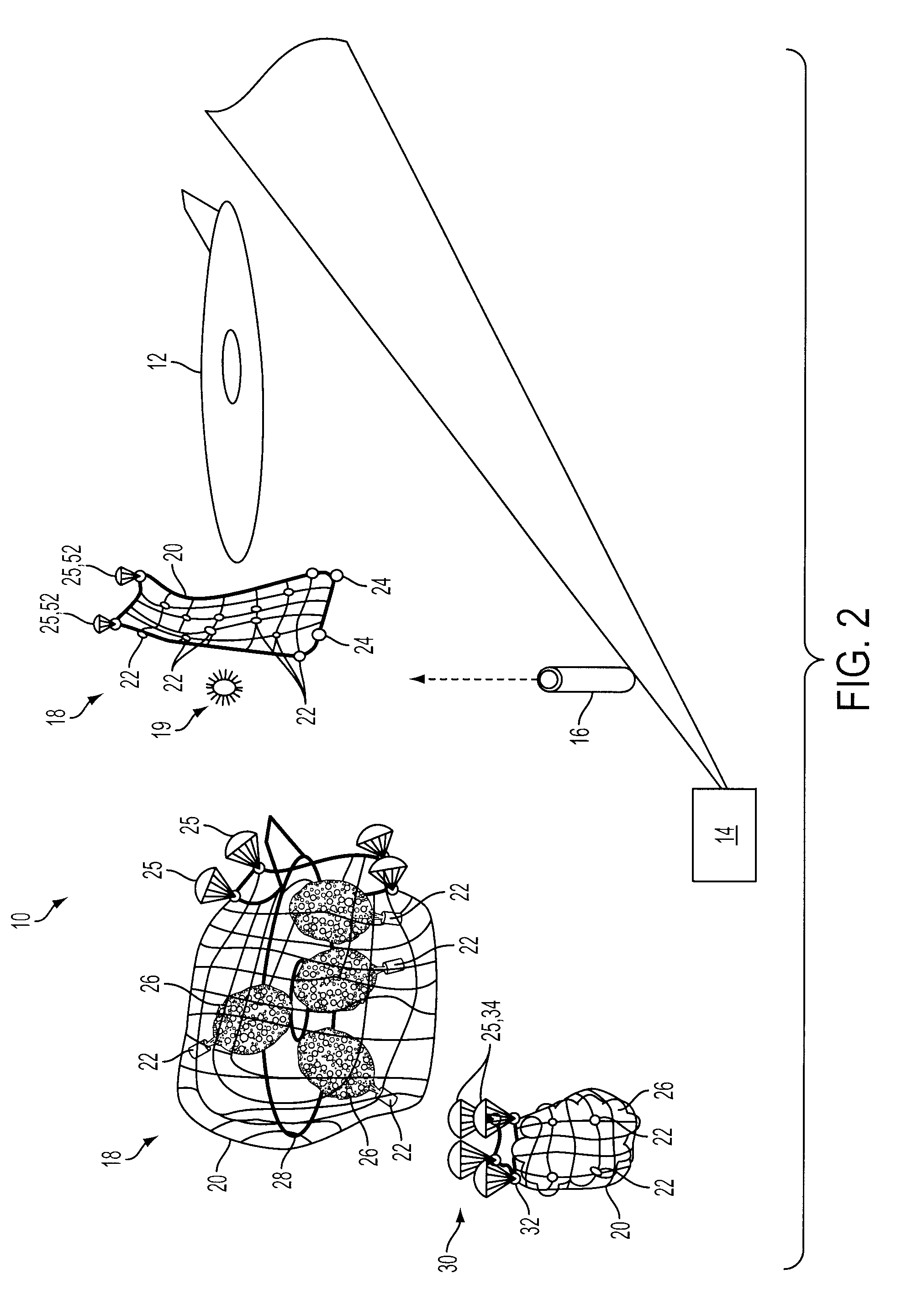
[0019]In one aspect, as shown in FIGS. 1-7, the present invention provides a catch and snare system 10 for an unmanned aerial vehicle 12 comprising: (a) a detection system 14, (b) a deployment system 16 in communication with the detection system 14, (c) a capture system 18 placed at an interference position by the deployment system 16, wherein the capture system 18 comprises a net 20, a plurality of foam deploying canisters 22 attached to the net 20 for deploying foam, and at least one canister 24 for deploying a decelerating parachute 25 attached to the net 20, wherein the foam 26 prevents the release of chemical or biological agents from the captured unmanned aerial vehicle 28 into the environment, and (d) a descent system 30 to bring the capture system 18 and a captured unmanned aerial vehicle 28 back to earth.

[0020]As used herein, there are a variety of detection systems known in the art for detecting an unmanned aerial vehicle (UAV) 12. For example, the detection system 14 may ...


PUM


Abstract

The present invention provides a catch and snare system for an unmanned aerial vehicle comprising: (a) a detection system, (b) a deployment system in communication with the detection system, (c) a capture system placed at an interference position by the deployment system, wherein the capture system comprises a net, a plurality of foam deploying canisters attached to the net for deploying foam, and at least one canister for deploying a decelerating parachute attached to the net, wherein the foam prevents the release of chemical or biological agents from the captured unmanned aerial vehicle, and (d) a descent system to bring the capture system and a captured unmanned aerial vehicle back to earth.

Description

BACKGROUND OF THE INVENTION[0001]There are systems in the art for intercepting intercontinental ballistic missiles, shoulder-launched rockets, and / or rocket propelled grenades. One example of an interception system operates by deploying a kill missile to destroy the incoming missile, which results in a debris field. Another example of an interception system involves launching a containment blanket made of Kevlar to contain the missile even if it detonates. Still further, an intercept device for flying objects exists that neither seriously damages nor destroys the flying object in question, but has a negative effect on its flying properties and then the intercept device destroys itself at a selected point in time so the flying object can return to its airfield unhindered and safely land.[0002]However, with the advent of the low cost unmanned aerial vehicle, which can carry a significant payload of biological or chemical weapons, these previous interception systems are ineffective. Sh...

Claims


Application Information

Patent Timeline
Patent Type & Authority Applications(United States)
IPC IPC(8): B64F1/02
CPCB64C2201/182F41H13/0006B64U70/30
Inventor GOOSSEN, EMRAY R.MARTINEZ, STEVEN D.
Owner HONEYWELL INT INC
Learn More