
Electronic status detection device

a technology of electronic status and detection device, which is applied in the direction of electric devices, instruments, transportation and packaging, etc., can solve the problems of relatively complicated and expensive, and the detection system of wireless switches described requires a relatively complex indicator circuit arrangement, so as to increase travel comfort and vehicle safety, the effect of simple structur

Inactive Publication Date: 2010-07-22
HUF HULSBECK & FURST GMBH & CO KG
View PDF5 Cites 3 Cited by
  • Summary
  • Abstract
  • Description
  • Claims
  • Application Information

AI Technical Summary

Benefits of technology

[0004]It is therefore an object of the present invention to solve at least some of the problems outlined with reference to the prior art and, in particular, to specify an apparatus which allows state detection in simplified and less expensive fashion.
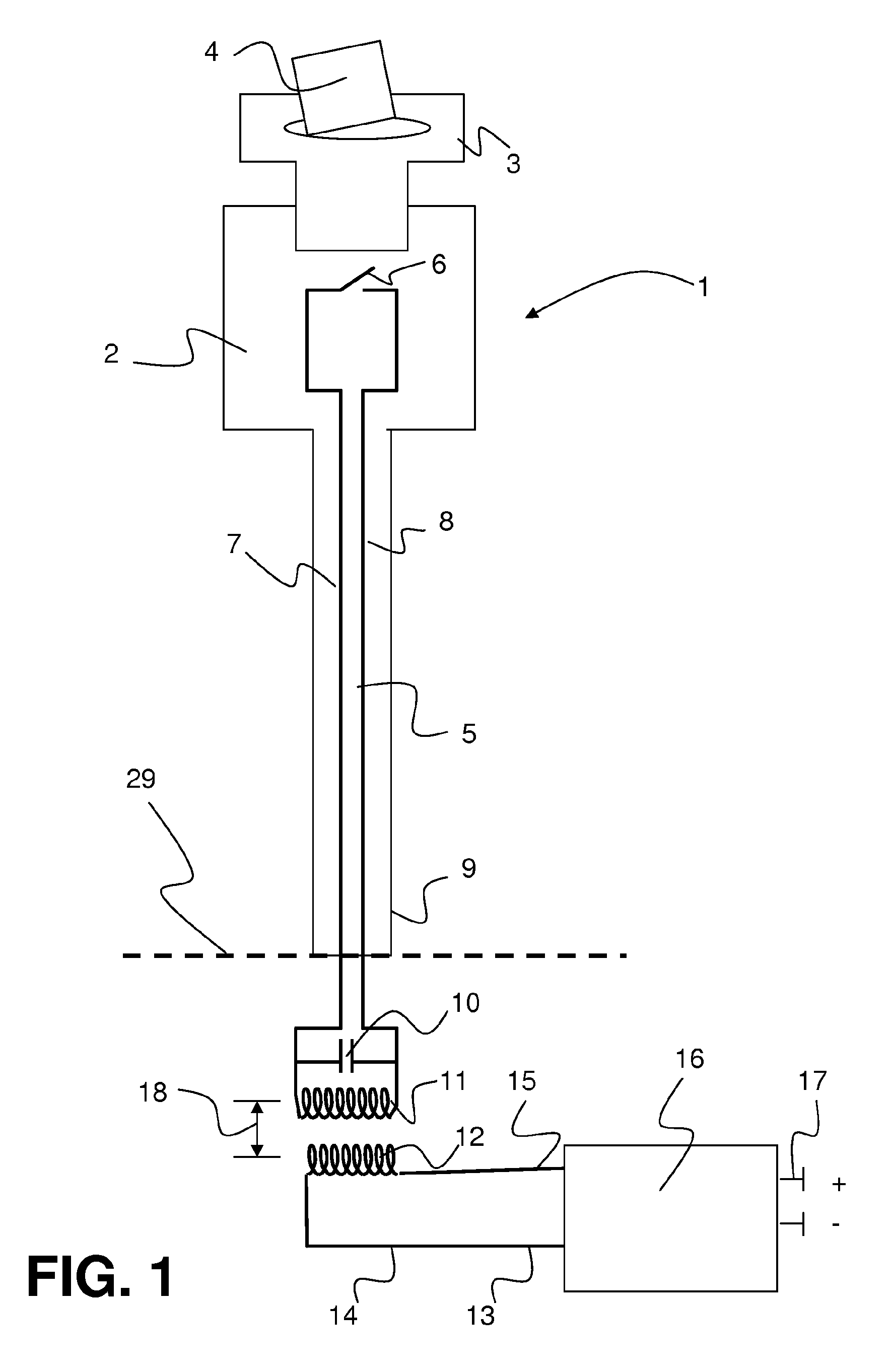
[0007]A fundamental idea of the present invention is to use an active and a passive resonant circuit for the state detection identification. This allows the passive resonant circuit to be of particularly simple, compact and inexpensive design. In this case, the passive resonant circuit is preferably arranged at the location at which a state can be detected. The active resonant circuit, for its part, is connected to a control device which, although it may be arranged in direct proximity to the passive resonant circuit, is usually accommodated at a distance therefrom at another location in the vehicle. In line with the present invention, this merely requires only parts of the respective resonant circuits not to exceed a maximum distance. A fundamental function of the state detection device according to the invention is that the control device feeds power into (only) one resonant circuit, as a result of which said circuit is operated actively.
[0010]It is particularly advantageous in this context if the passive resonant circuit has only passive electronic components. Such passive electronic components are coils or capacitors, for example. These components can be combined to form two groups. One group is formed by capacitive components whereas another group is formed by inductive components. In addition to the capacitive and inductive components, it is then also necessary to provide supply line means for electronically connecting the components and circuit devices. All of these are passive components which are used in the passive resonant circuit. The switching devices are used for detecting the different states. They allow a particularly simple and distinctive, explicit way of altering the oscillatory characteristic of the passive resonant circuits on the basis of states of the apparatus which is to be monitored. If such a switch is arranged in a resonant circuit comprising a capacitor and a coil, for example, then it may be open in a first state, for example, when the resonant circuit is capable of oscillation. In a second state, the switch may then be closed and bypass both the capacitive component and the inductive component, as a result of which the resonant circuit is incapable of oscillation. This is a particularly simple, inexpensive and reliable embodiment of the invention. Alternatively, it is also possible for other passive components to be used, however, which can alter their physical properties on the basis of states which are to be monitored. In particular, electrical resistor components, capacitive components or inductive components which change their properties on the basis of states of the device which is to be monitored are suitable for this.
[0014]It is therefore particularly advantageous if the resonant circuits have inductive components which comply with the maximum distance.
[0017]As already mentioned previously, it is quite particularly advantageous within the context of the invention if at least part of a passive resonant circuit is arranged in a belt buckle. In the case of this application, the present invention can be used to produce a particularly simple, reliable and durable device which is used for detecting the use state of the belt buckle.
[0018]Furthermore, the object according to the invention is solved by providing for a motor vehicle to be equipped with at least one state detector, the latter being designed in line with the invention and being connected for control purposes to at least one control device of the motor vehicle. It therefore becomes possible to take account of the information supplied from the state detection device with regard to the respective vehicle state when controlling the overall vehicle. The information can thus be used further in a control device of the motor vehicle and can thus be used to increase travel comfort and vehicle safety.

Problems solved by technology

Whereas such an apparatus allows intended state detection to be performed for apparatuses in vehicles, the wireless switch detection system described requires the arrangement of a relatively complex indicator circuit.
This makes it relatively complicated and expensive.

Method used


Image

  • Electronic status detection device
  • Electronic status detection device
  • Electronic status detection device

Examples


Embodiment Construction

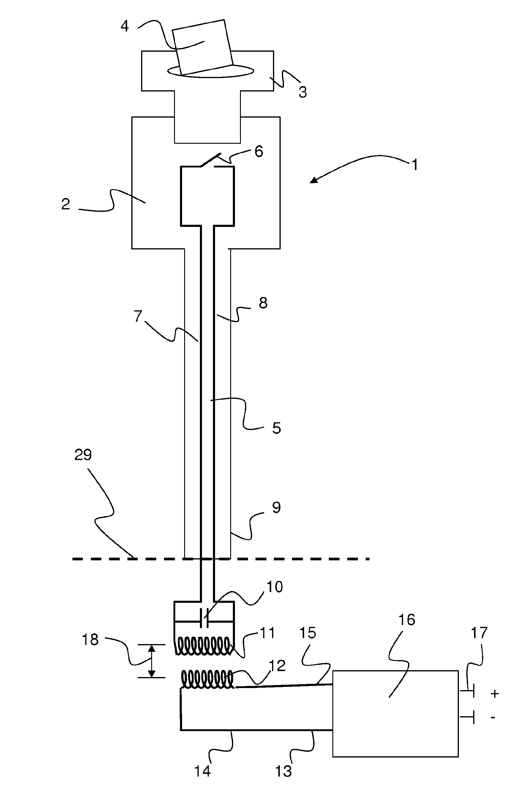
[0029]FIG. 1 shows a belt buckle 1 designed in accordance with the invention in a schematic side view. The belt buckle 1 has a housing 2 which accommodates the mechanical part—which is not shown here—of the belt buckle. The belt buckle 1 has a belt clip 3 inserted into it on which a belt strap 4 is turned around. The housing 2 also partially accommodates a passive resonant circuit 5. In the embodiment shown, the housing 2 contains a switch 6 and a portion of a first electrical line 7 and of a second electrical line 8 within the housing 2. A buckle stalk 9 projects downward out of the housing 2. The buckle stalk 9 is then mounted on the vehicle 29, further comments concerning the mechanical mounting of the buckle stalk 9 being dispensed with at this juncture. In parallel with the buckle stalk 9, the first line 7 and the second line 8 are routed downward, to where the further components of the passive resonant circuit 5 are located. In this case, the passive resonant circuit 5 has a c...


PUM


Abstract

An electronic status detection device for wireless detection of at least one status of an apparatus, wherein the status detection device comprises at least two resonant circuits, of which at least one resonant circuit is active and one resonant circuit is passive, wherein the active resonant circuit comprises at least one control device. A status detection device such as this makes it possible, for example, to reliably detect the presence or the absence of belt clips in safety belt locks.

Description

BACKGROUND OF THE INVENTION[0001]The present invention relates to an electronic state detection device for vehicles for wirelessly detecting at least one state of an apparatus. Furthermore, the present invention also relates to a motor vehicle having at least one state detection device. The invention is used for monitoring states of at least one appliance or one apparatus in vehicles and is used particularly in the automotive sector.[0002]In modern vehicles, it is increasingly necessary to monitor states and functions, and components, appliances, units or apparatuses contained therein. This can be derived partly from legal regulations, and also from the aim of improving safety for vehicle occupants or increasing comfort, for example. Thus, in modern vehicles, the proper closing of doors, the fastening of safety belts and / or the depression of the brake pedal when starting automatic vehicles is monitored, for example. In addition, seat occupancy identification can also be covered by t...

Claims


Application Information

Patent Timeline
IPC IPC(8): G01R27/32B60L1/00
CPCH01H9/167H04B5/0075H01H9/168H04B5/24
Inventor HILD, SVENSCHNEIDER, MARTINRIEFERS, STEFANJENDRITZA, DANIEL
Owner HUF HULSBECK & FURST GMBH & CO KG
Learn More