
Line Head and Image Forming Apparatus

a technology of image forming apparatus and line head, which is applied in the direction of electrographic process apparatus, printing, instruments, etc., can solve the problems of concentration unevenness and concentration unevenness, and achieve the effect of preventing a variation of spot size, substantially constant spot size, and preventing concentration unevenness in the formed latent imag

Inactive Publication Date: 2010-07-22
SEIKO EPSON CORP
View PDF30 Cites 4 Cited by
  • Summary
  • Abstract
  • Description
  • Claims
  • Application Information

AI Technical Summary

Benefits of technology

[0009]An advantage of some aspects of the invention is that it provides a line head capable of performing a high-accuracy exposure process and an image forming apparatus capable of obtaining a high-quality image.
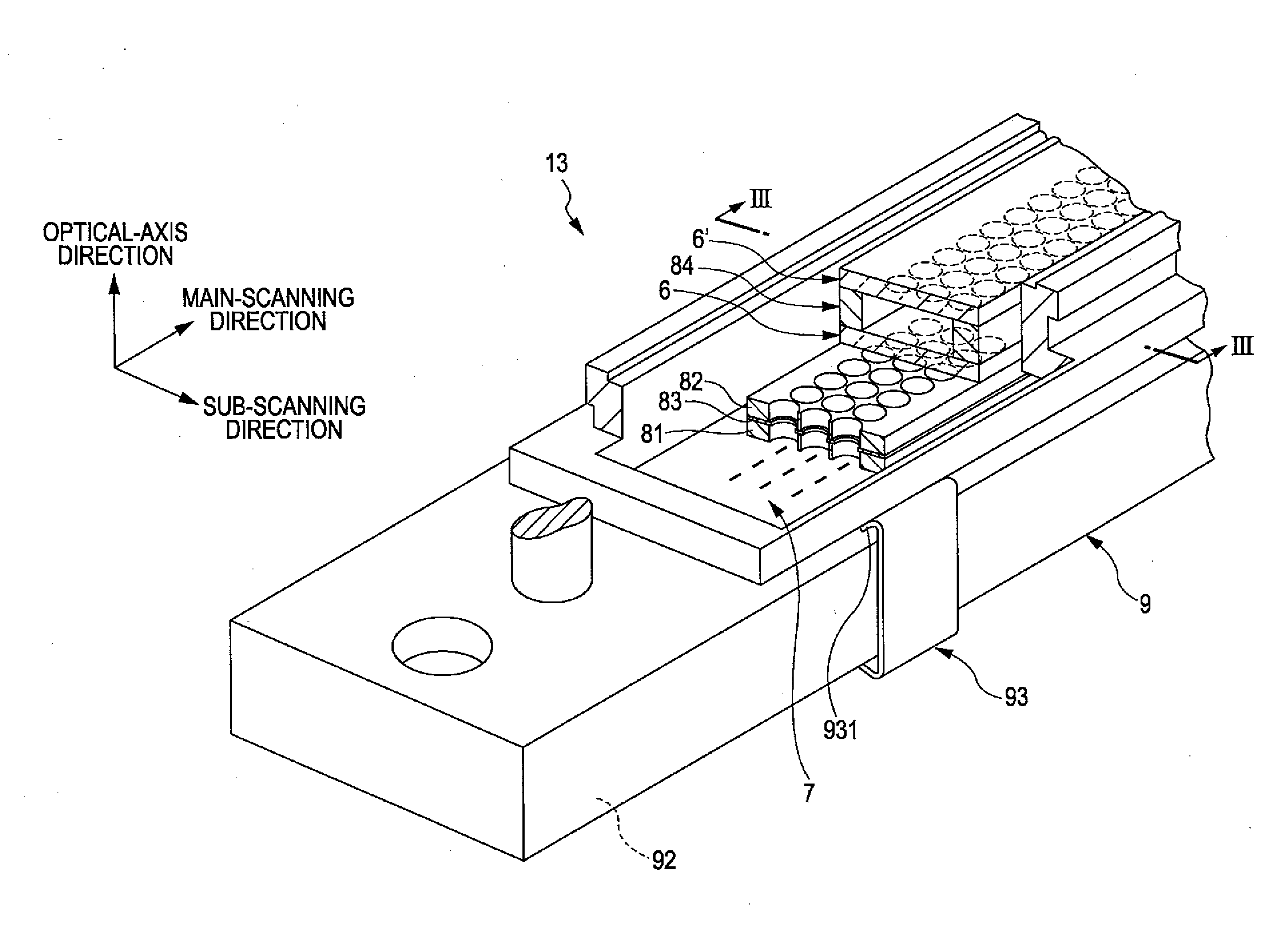
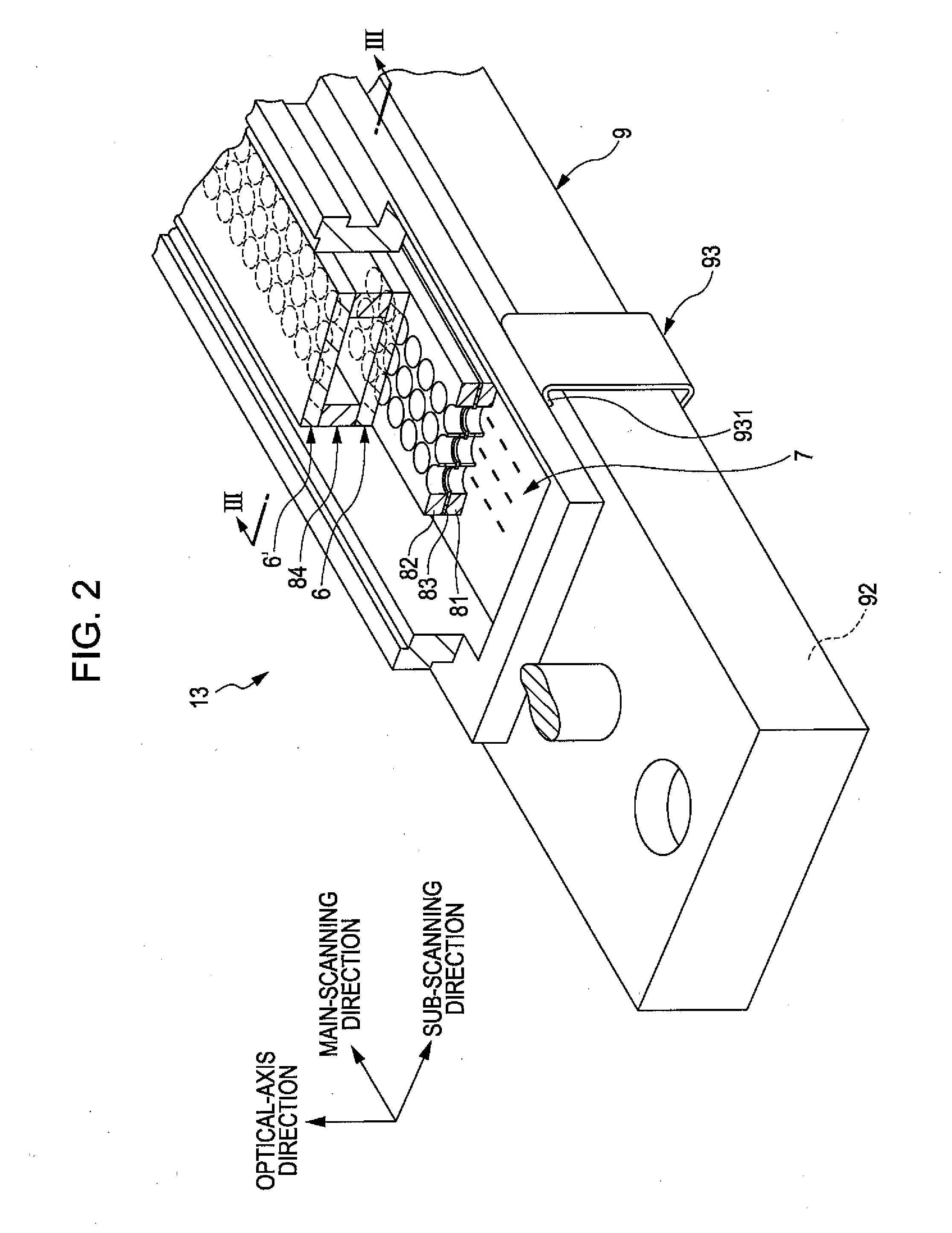
[0019]According to the line head of the aspects and embodiments of the invention having the above-described configuration, since the optical system has the lens (multifocal lens) having a plurality of focal points, when the light emitted from the light-emitting element is imaged by the optical system, it is possible to make the spot size of the light substantially constant over a relatively wide range in the optical axis direction in the vicinity of the image surface. Therefore, even when the positional relationship in the optical axis direction between the image surface and the light irradiation surface, is changed or offset, it is possible to prevent a variation of the spot size on the light irradiation surface. As a result, it is possible to prevent concentration unevenness in the formed latent image. In particular, since the lens (multifocal lens) having a plurality of focal points is located closest to the side of the aperture diaphragm (the side of the light-emitting elements), the optical system can reliably exhibit the above-described characteristics even when the light-emitting elements are located at different distances from the optical axis (namely, even when the angles of view are different). Therefore, the line head of the invention is able to realize a high-accuracy exposure process.
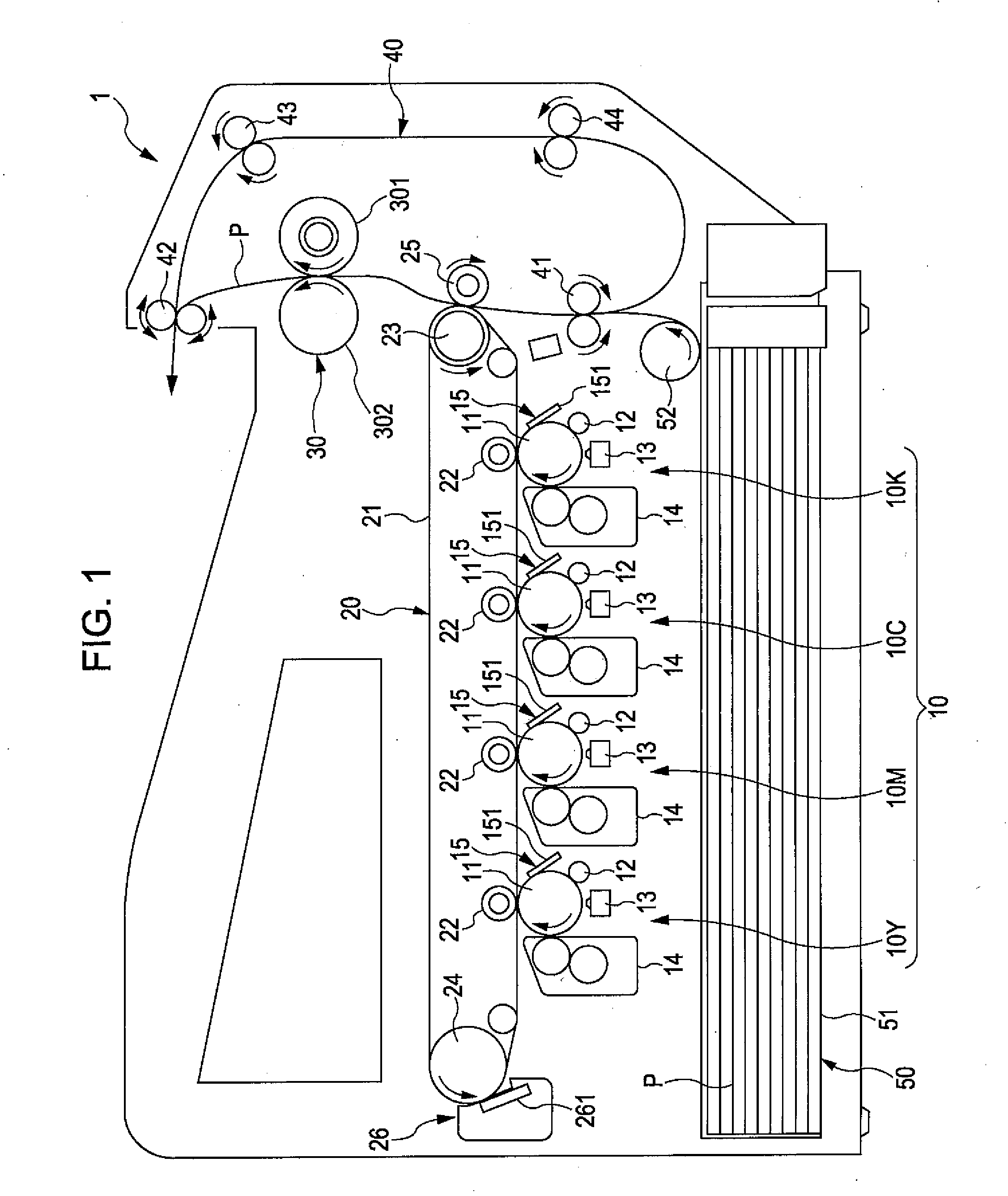
[0020]Moreover, according to the image forming apparatus of the aspect of the invention, by realizing the above-described high-accuracy exposure process, it is possible to obtain a high-quality image in which concentration unevenness is suppressed.

Problems solved by technology

As a result, the concentration of the latent image formed on the surface of the photoconductor becomes different between pixels, which are formed by the light from the LED located close to the optical axis of the convex lens element, and pixels, which are formed by the light from the LED located distant from the optical axis of the convex lens element, whereby concentration unevenness occurs.
Furthermore, the positional relationship between the image surface of the convex lens element and the light irradiation surface (the surface of the photoconductor) is offset or varied due to errors in mounting the line head onto the body of the image forming apparatus, eccentricity of the photoconductor, or the like.
In this respect, concentration unevenness will occur.

Method used


Image

  • Line Head and Image Forming Apparatus
  • Line Head and Image Forming Apparatus
  • Line Head and Image Forming Apparatus

Examples


examples

[0175]Hereinafter, specific examples of the invention will be described.

example

[0176]A line head having the optical system as illustrated in FIG. 9 was produced. FIG. 9 is a cross-sectional view taken along the main-cross section, illustrating the optical system included in the line head according to Example of the invention.

[0177]The line head of the present example had the same configuration as the line head illustrated in FIGS. 3 and 5, except that three light-emitting elements 74 were arranged in the main-scanning direction.

[0178]Here, in the main-cross section, the three light-emitting elements 74 arranged in the main-scanning direction were arranged symmetrically to the optical axis.

[0179]Moreover, a glass material was used as the constituent material of the support portions 65 and 65′, and a resin material was used as the constituent material of the lenses 64 and 64′.

[0180]The surface configuration of the optical system of the line head is shown in Table 1.

TABLE 1RefractiveCurvature at theindex atcenter of main-SurfacereferenceSurface numbercross sectio...


PUM


Abstract

An image forming apparatus includes a latent image carrier on which a latent image is formed; and a line head. The line head includes light-emitting elements arranged in a first direction; an aperture diaphragm; and an optical system that images light emitted from the light-emitting elements on a latent image carrier. The aperture diaphragm and the optical system are arranged in a second direction that is orthogonal to or substantially orthogonal to the first direction; and among the lenses included in the optical system, a lens located at the position closest to the aperture diaphragm is a multifocal lens.

Description

BACKGROUND[0001]1. Technical Field[0002]The present invention relates to a line head and an image forming apparatus.[0003]2. Related Art[0004]Electrophotographic image forming apparatuses such as copying machines or printers are provided with an exposure unit that performs an exposure process on an outer surface of a rotating photoconductor so as to form an electrostatic latent image thereon. As the exposure unit, a line head having a structure in which a plurality of light-emitting elements is arranged in the direction of the rotation axis) of the photoconductor is known (for example, see JP-A-2-4546)[0005]As the line head, for example, JP-A-2-4546 describes an optical information writer in which a plurality of LED array chips with a plurality of LEDs (light-emitting elements) is arranged in one direction.[0006]In the optical information writer, the plurality of LEDs of each of the LED array chips is arranged in the direction of the rotation axis of the photoconductor. Convex lens ...

Claims


Application Information

Patent Timeline
IPC IPC(8): G03G15/04
CPCB41J2/451G03G2215/0412G03G15/04072
Inventor SOWA, TAKESHINOMURA, YUJIROKOIZUMI, RYUTA
Owner SEIKO EPSON CORP
Learn More