Electrostatically applying a label to a mold cavity

a label and mold cavity technology, applied in the direction of chemistry apparatus and processes, glue vessels, lamination ancillary operations, etc., can solve the problems of inability to provide satisfactory labeling in conventional in-mold labeling processes and apparatus, and the difficulty of holding the label in place during injection of plasticized materials, etc., to achieve more reliable and cost-effective effects

Inactive Publication Date: 2010-07-29
ILLINOIS TOOL WORKS INC
View PDF17 Cites 13 Cited by
  • Summary
  • Abstract
  • Description
  • Claims
  • Application Information

AI Technical Summary

Benefits of technology

[0008]In some applications, electrostatics offers a more reliable and cost-effective alternative to the use of a vacuum for holding the label in its proper location in the die/cavity. In one typical electrostatic process, an automated machine picks up a label from the magazine using a mandrel with vacuum ports and holes incorporated therein. While the label is being held by the mandrel, a static charge is placed on the label as the mandrel with the label approaches the mold. When the mandrel and label have been placed into the mold cavity, the mandrel vacuum is released and the label is transferred to the surface of the die due to electrostatic forces. No vacuum in

Problems solved by technology

Although in-mold labeling presents many technical challenges, one of the most difficult is how the label is held in place during injection of the plasticized material.
The two label-holding techniques that are presently in use rely on either a vacuum and/or electrostatics and each of these techniques faces a different set of problems.
While the aforementioned apparatus and techniques have

Method used


Image

  • Electrostatically applying a label to a mold cavity
  • Electrostatically applying a label to a mold cavity
  • Electrostatically applying a label to a mold cavity

Examples


Embodiment Construction

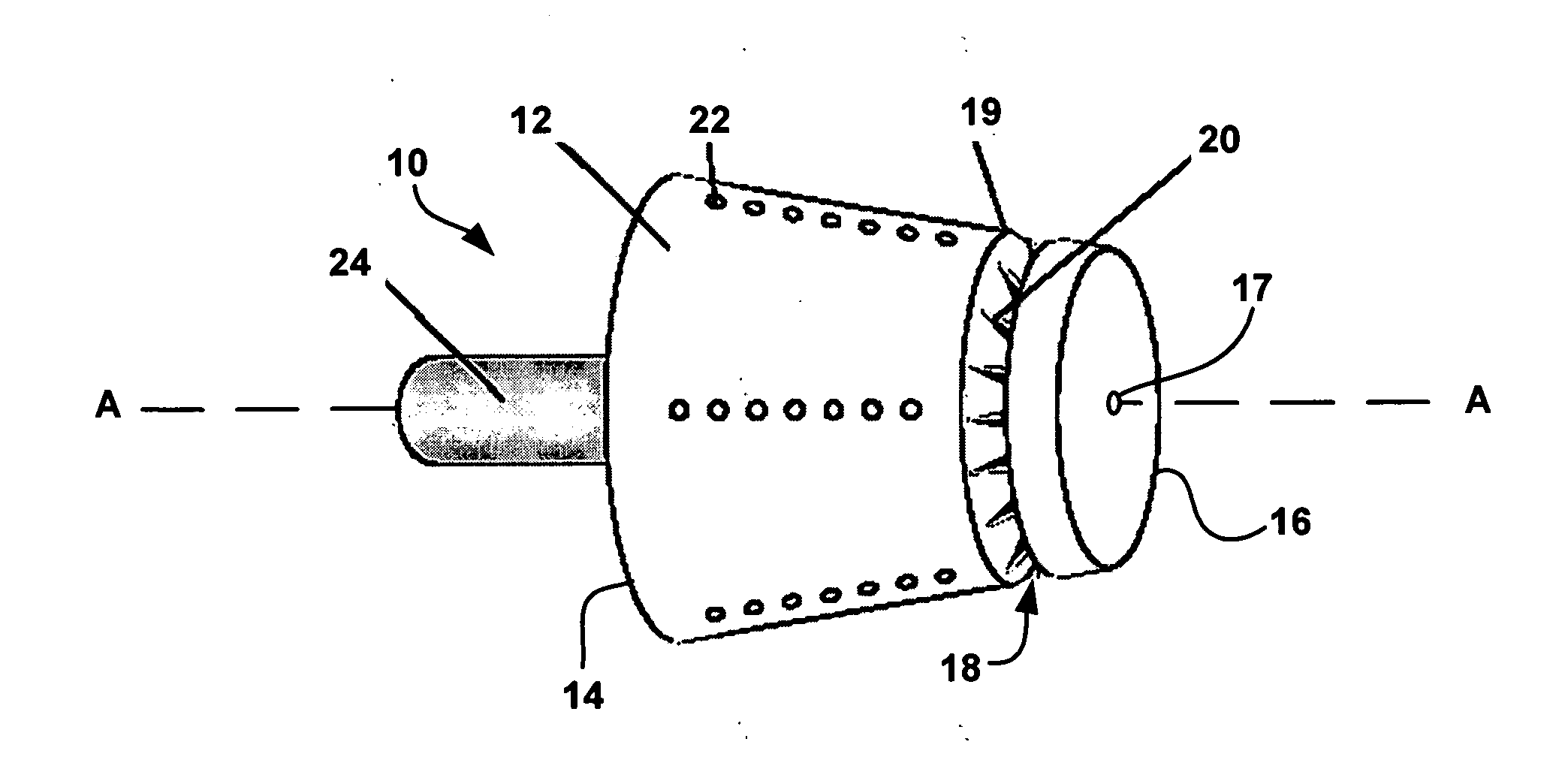
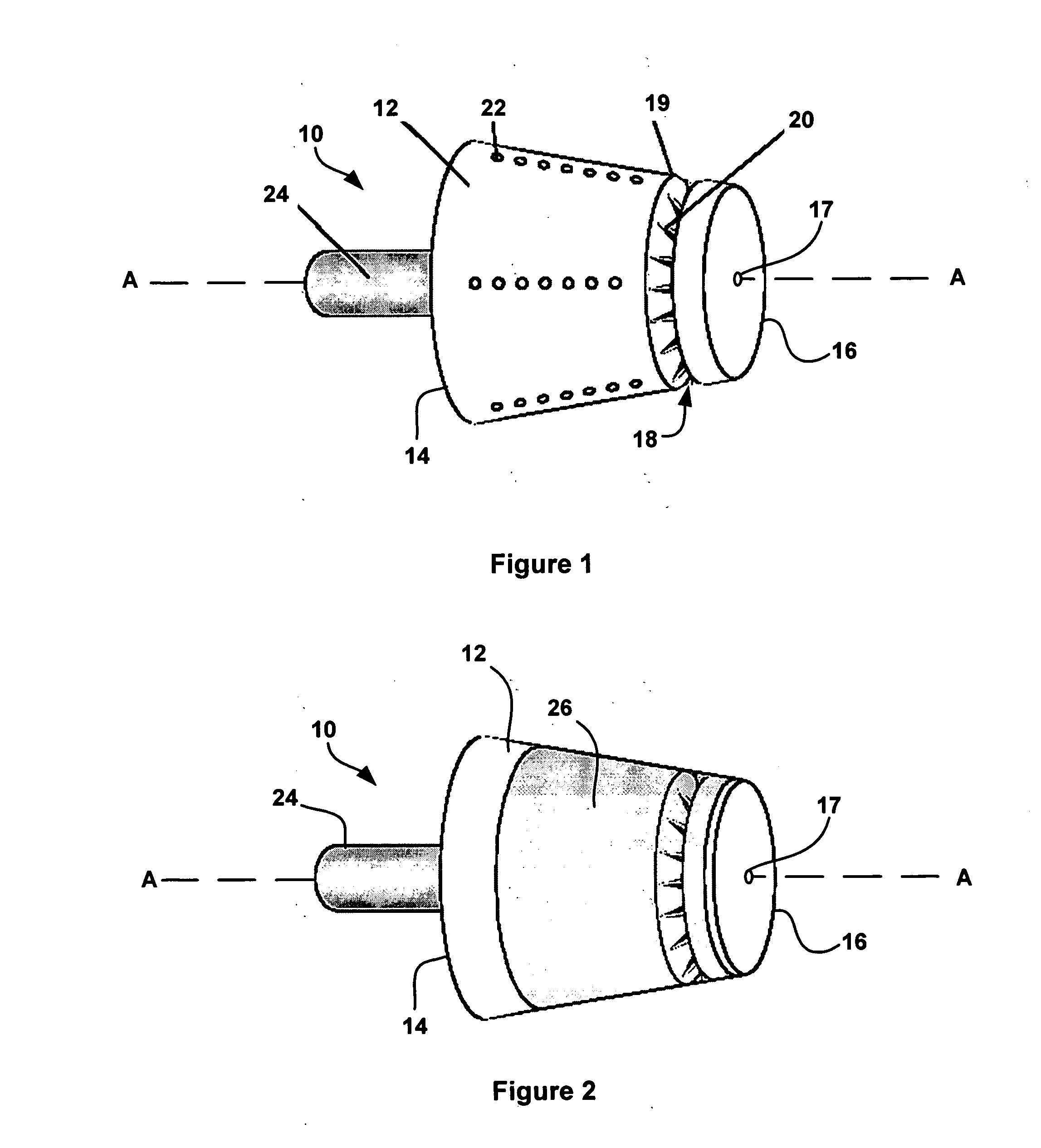
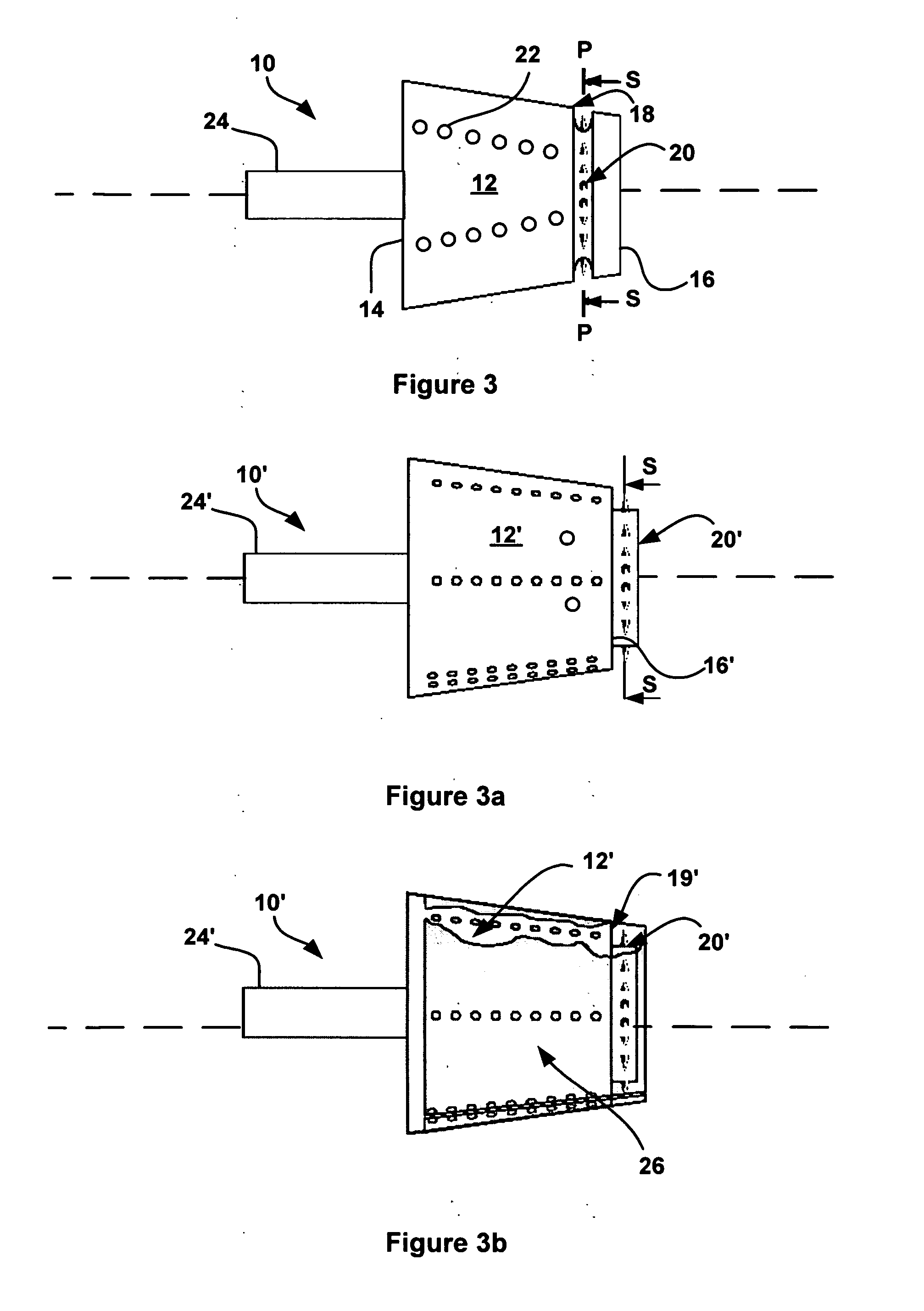
[0026]With primary reference to FIG. 1, a first preferred embodiment of the present invention is directed to an electrostatic mandrel 10 capable of positioning a label in a female mold cavity. The mandrel may include a body 12 (that defines an axis A), with a first end 14 and an opposite distal end 16, a set of ionizing electrodes 20, a groove 18 disposed about body 12 and in a plane P (see FIG. 3) that is at least substantially perpendicular to axis A. Mandrel 12 may, optionally, also include an axially aligned guide shaft to facilitate compatibility with conventional in-mold labeling apparatus. In this form of the invention, groove 18 is located near distal end 16 of mandrel 10 and set of ionizing electrodes 20 includes plural ionizing electrodes with ionizing tips positioned within mandrel groove 18 (below the surface of body 12). When an appropriate high voltage is applied to electrode set 20, a substantially uniform ionizing current is emitted from the electrodes 20 in the groo...


PUM

PropertyMeasurementUnit
Lengthaaaaaaaaaa
Lengthaaaaaaaaaa
Timeaaaaaaaaaa

Abstract

The disclosure describes the use of electrostatics to in-mold labeling wherein a label is secured to a mandrel with an axis-defining body, a first end, a distal end, a set of ionizing electrodes disposed about the body, near the distal end, and in a plane perpendicular to the axis. When the mandrel is positioned in a mold cavity, the label is released and a varying voltage applied to the electrodes to form a substantially uniform and ring-like source of ionizing current. The ionizing current progressively pins the label against the die as the mandrel is withdrawn from the die until substantially the entire label is pinned. The ionizing current may then be ended and the mandrel removed so that an article may then be formed into the label.

Description

CROSS REFERENCE TO RELATED CASES[0001]This application claims the benefit under 35 U.S.C. 119(e) of co-pending U.S. Provisional Application(s) Ser. No. 60 / 930,238 filed May 15, 2007 and entitled “Electrostatically Applying a Label to a Mold Cavity”; which Provisional Application is hereby incorporated by reference.BACKGROUND OF THE INVENTION[0002]1. Field of the Invention[0003]The present invention is directed to systems, processes and apparatus for use in manufacturing molded articles having integrally formed labels. More particularly, the invention relates to the use of electrostatics to improve the quality and efficiency of the aforementioned manufacturing processes. Accordingly, the general objects of the invention are to provide novel systems, methods and apparatus of such character.[0004]2. Description of the Related Art[0005]“In-Mold Labeling” has become increasingly popular in recent years and generally includes applying a label to the wall of the mold (die) cavity, closing ...

Claims


Application Information

Patent Timeline
IPC IPC(8): B29C65/00B29C65/14
CPCB29C31/008B29C2045/14057B29C45/14008
Inventor BLITSHTEYN, MARK
Owner ILLINOIS TOOL WORKS INC
Why Eureka
Try Eureka