
Actuator subassembly

a technology of actuators and sub-assemblies, which is applied in the direction of manufacturing tools, pedestrian/occupant safety arrangements, vehicular safety arrangements, etc., can solve the problems of excessive oversized and expensive conventional explosive studs used in these applications, and achieve the effect of reducing mounting effort and easy production

Active Publication Date: 2010-07-29
TRW AIRBAG SYST +1
View PDF26 Cites 12 Cited by
  • Summary
  • Abstract
  • Description
  • Claims
  • Application Information

AI Technical Summary

Benefits of technology

[0012]In the igniting portion preferably a pre-fabricated electric igniting unit including a pyrotechnic charge is accommodated. In this way, the pyrotechnic actuator unit can be manufactured at very low cost.
[0018]In another embodiment of the actuator subassembly the receiving element includes catch portions forming a snap fit with the holding portion. This snap fit permits a particularly simple mounting of the actuator unit on the receiving element.
[0020]The receiving element is preferably engaged in the modular component. This snap fit permits simple and easy assembly of the actuator subassembly at the modular component.
[0028]In an advantageous method variant, in step b) the pre-fabricated actuator unit is fastened to the receiving element by means of snap fit. As this snap fit can be easily brought about without any tool, this method step requires a minimum mounting effort.
[0029]Moreover, the receiving element can preferably be opened and closed, wherein the actuator unit in step b) is inserted in the opened receiving element while forming the snap fit and the snap-fit connection is secured against loosening when the receiving element is closed. Due to this securing of the snap-fit connection the actuator unit is attached to the receiving element in an extremely reliable manner.

Problems solved by technology

Conventional explosive studs are frequently oversized and too expensive for these applications.

Method used


Image

  • Actuator subassembly
  • Actuator subassembly
  • Actuator subassembly

Examples


Embodiment Construction

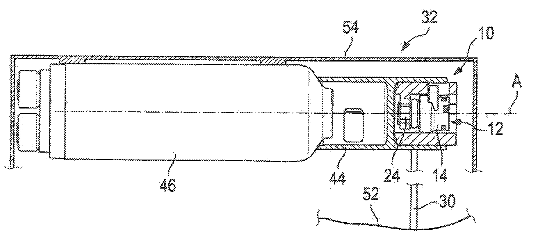
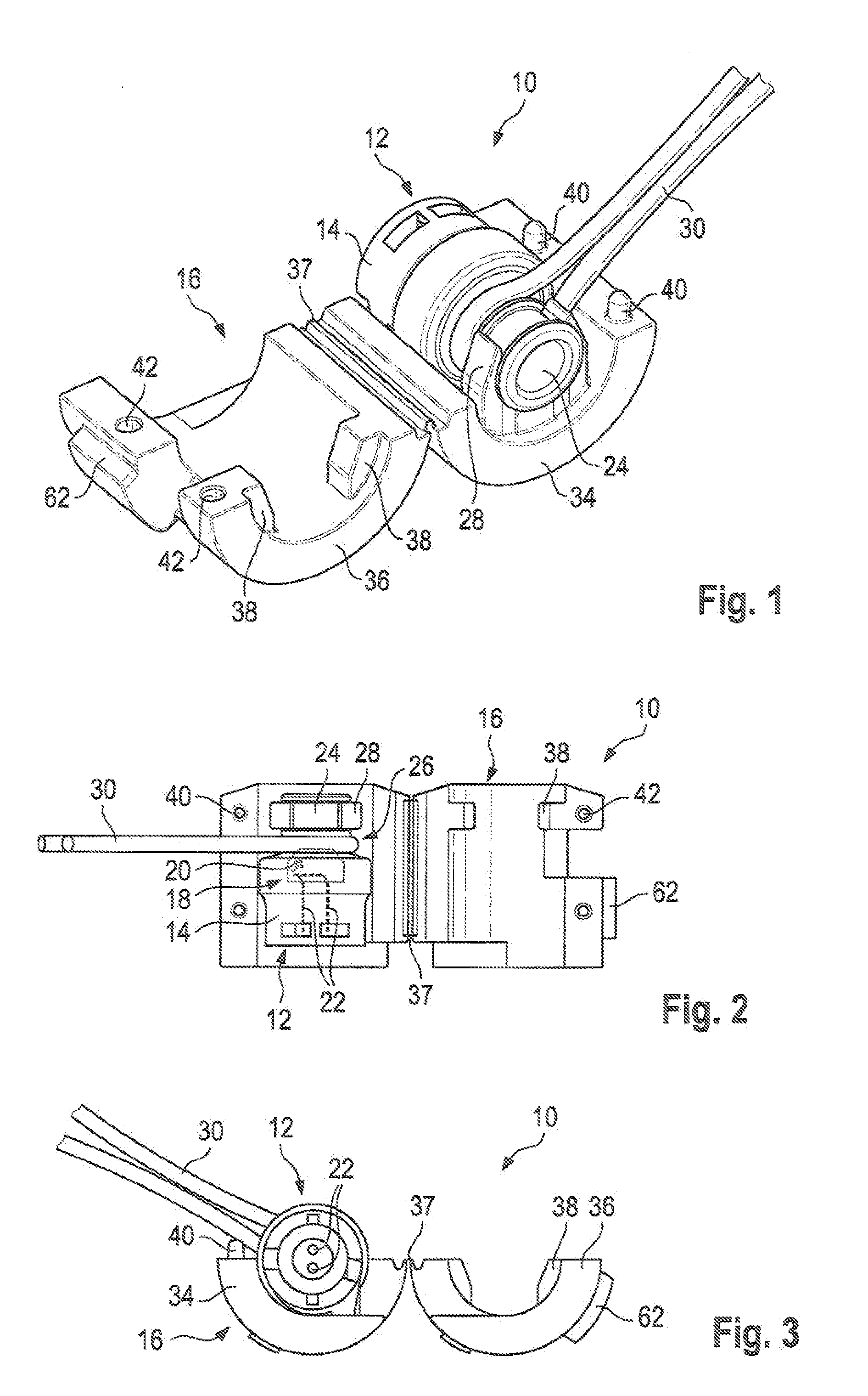
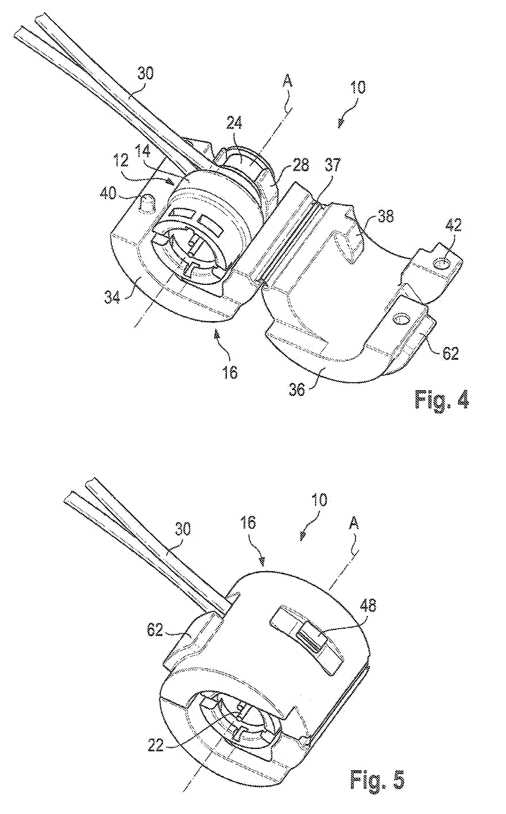
[0045]FIG. 1 illustrates an actuator subassembly 10 for a vehicle safety system comprising a pyrotechnic actuator unit 12 having an igniting portion 14 as well as comprising a receiving element 16 forming a guide for the movable igniting portion 14 after activating the actuator unit 12. The pyrotechnic actuator unit 12 can especially be a pre-fabricated TAU (tether activation unit) mentioned in the beginning, as described, for instance, in WO 2007 / 065715A1, this document being expressly referred to in toto.

[0046]In the igniting portion 14 of the actuator unit 12 a pre-fabricated electric igniting unit 18 including a pyrotechnic charge 20 is received. The electric igniting unit 18, also referred to as igniter, and the pyrotechnic charge 20 are indicated in broken lines in the top view according to FIG. 2. Metallic contact pins 22 of the igniting unit 18 extend into a hollow of the igniting portion 14, the hollow forming a bushing for receiving a plug-in connector (not shown) which tr...


PUM

PropertyMeasurementUnit
breaking pointaaaaaaaaaa
shapeaaaaaaaaaa
forcesaaaaaaaaaa

Abstract

The invention relates to an actuator subassembly (10) for a vehicle safety system comprising a pyrotechnic actuator unit (12) including an igniting portion (14) as well as a receiving element (16) forming a guide for the movable igniting portion (14) after activating the actuator unit (12). Further the invention relates to an airbag module of a vehicle safety system comprising said actuator subassembly (10) and a method of mounting a releasable tether (30) on an airbag module by means of said actuator assembly (10).

Description

FIELD OF THE INVENTION[0001]The invention relates to an actuator subassembly for a vehicle safety system comprising a pyrotechnic actuator unit having an igniting portion. Moreover, the invention also relates to an airbag module of a vehicle safety system comprising an actuator subassembly of this type as well as a method of mounting a releasable tether at an airbag module by means of an actuator assembly.BACKGROUND OF THE INVENTION[0002]In engineering, especially in vehicle safety engineering, explosive studs are employed as actuator units. As a rule, they are extremely robust metal parts that are fastened by a thread and are capable of absorbing excessive forces. The required activating energy of these explosive studs is correspondingly high so that they expose housing orifices, displace component parts (sometimes against a pressing force) or cut themselves in two, for instance.[0003]In the case of modern vehicle safety systems, especially in the case of airbag modules, it is ende...

Claims


Application Information

Patent Timeline
Patent Type & Authority Applications(United States)
IPC IPC(8): B60R21/33B60R21/16F15B15/19B23P11/00B23P11/02B60R21/2338B60R21/26
CPCB60R21/2338B60R2021/23388Y10T29/49826B60R2021/26029Y10T29/49876B60R2021/2395
Inventor DEBLER, JENSSEDLMEIER, MARTINENGLBRECHT, KARL
Owner TRW AIRBAG SYST
Learn More