Method for producing slip ring brushes and slip ring brushes made thereby

a technology slip ring brushes, which is applied in the direction of current collectors, fixed connections, electrical devices, etc., can solve the problems of high cost and time consumption of mounting the corresponding slip ring brushes, and the quality of the spring properties of slip ring brushes produced in this manner is not optimal, so as to achieve the effect of small required space and minimal mounting effor

Active Publication Date: 2005-06-21
LTN SERVOTECHN
View PDF7 Cites 3 Cited by
  • Summary
  • Abstract
  • Description
  • Claims
  • Application Information

AI Technical Summary

Benefits of technology

[0006]It is an aspect of the present invention to provide a method for producing a slip ring brush which may involve minimum mounting effort and whereby qualitatively high-value slip ring brushes may be producible, using a small required space.
[0007]In addition, a slip ring brush may be provided by which the service life and the reliability of slip ring units may be significantly increased.

Problems solved by technology

This production method has the disadvantage, among other things, that it is comparatively costly and time-consuming.
This method of construction has the disadvantage that the mounting of the corresponding slip ring brush is expensive.
In addition, slip ring brushes produced in this manner have a non-optimal quality with respect to their spring properties.

Method used


Image

  • Method for producing slip ring brushes and slip ring brushes made thereby
  • Method for producing slip ring brushes and slip ring brushes made thereby
  • Method for producing slip ring brushes and slip ring brushes made thereby

Examples


Embodiment Construction

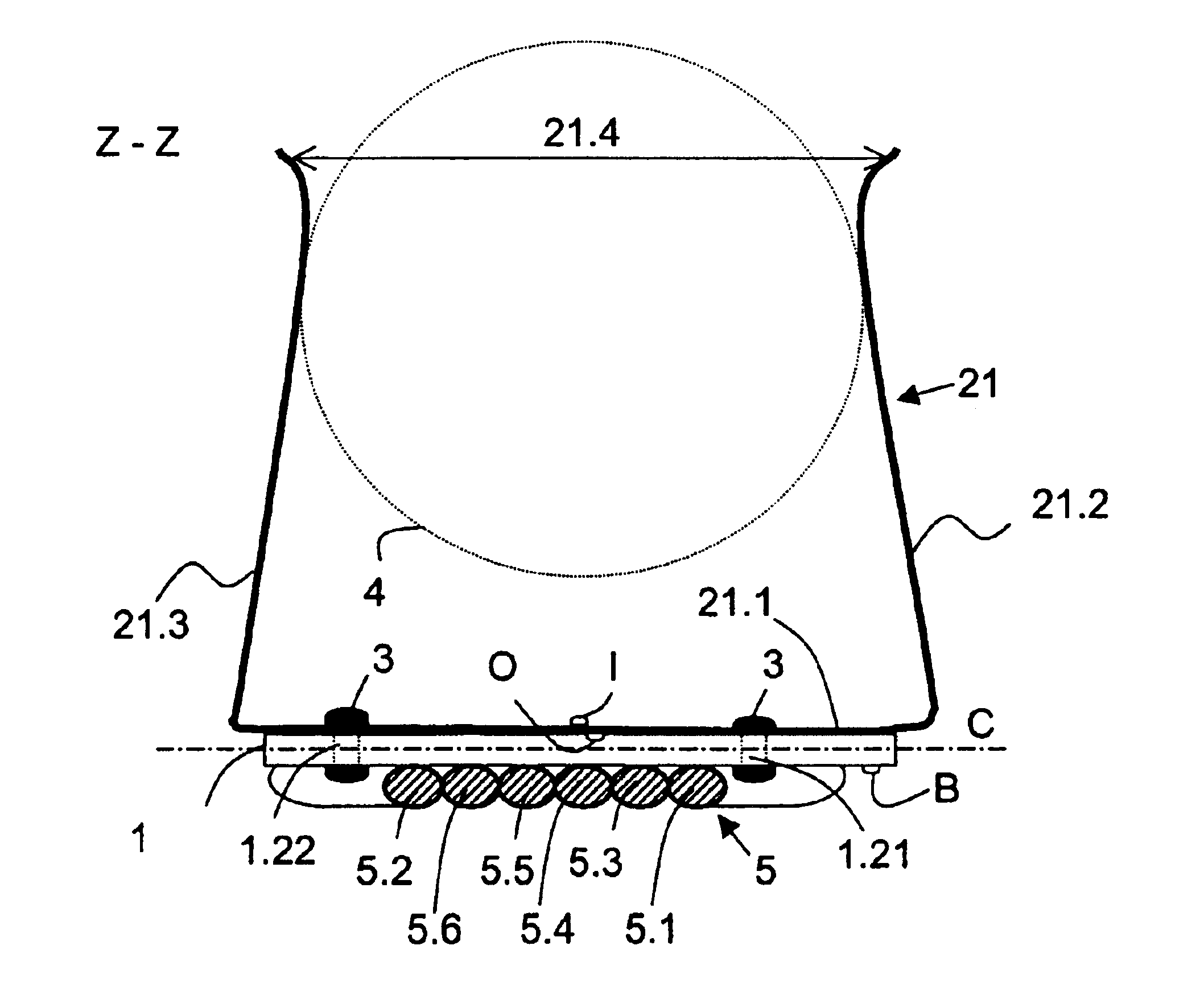
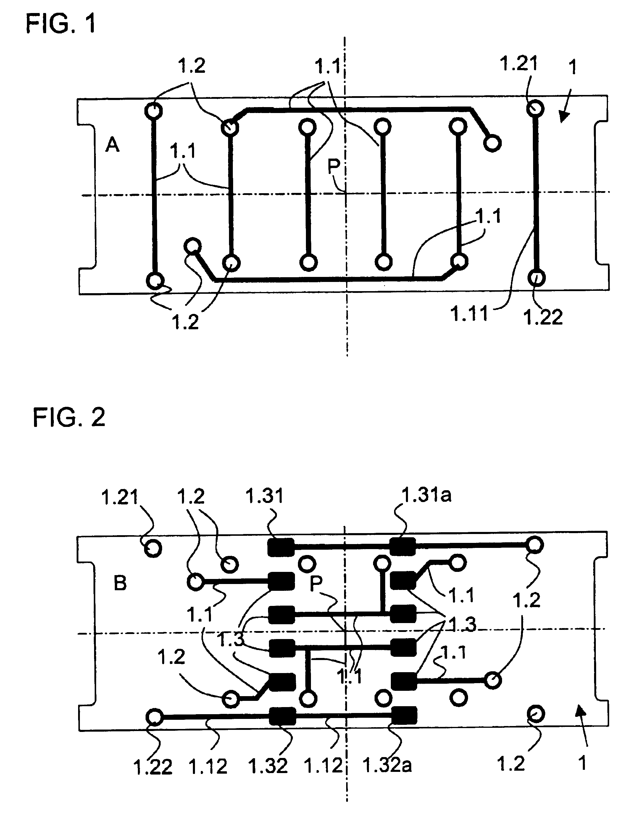
[0030]FIG. 1 shows a top view of a first surface A of a printed circuit board 1. On this surface A, there are printed circuit traces 1.1, 1.11, made of copper in the example shown, which end at bores 1.2, 1.21, 1.22. These bores 1.2, 1.21, 1.22, which penetrate printed circuit board 1 all the way through, are metallized, so that they are metallically coated on their inner walls, as well as ring-shaped at their inner wall edges, using tin in the example shown. Printed circuit board 1 is made of epoxy resin filled with glass fibers, and it has a comparatively low heat conductivity. Alternatively, other materials may also be used for printed circuit board 1, such as materials based on polyamide components, ceramic components, etc.

[0031]FIG. 2 shows a top view onto a second surface B of printed circuit board 1. In this view, besides bores 1.2, 1.21, 1.22 and additional circuit traces 1.1, 1.12, pads 1.3, 1.31, 1.31a, 1.32, 1.32a are shown. Parallel to the plane of the drawing of FIGS. 1...


PUM

PropertyMeasurementUnit
diameteraaaaaaaaaa
electric poweraaaaaaaaaa
heat conductivityaaaaaaaaaa

Abstract

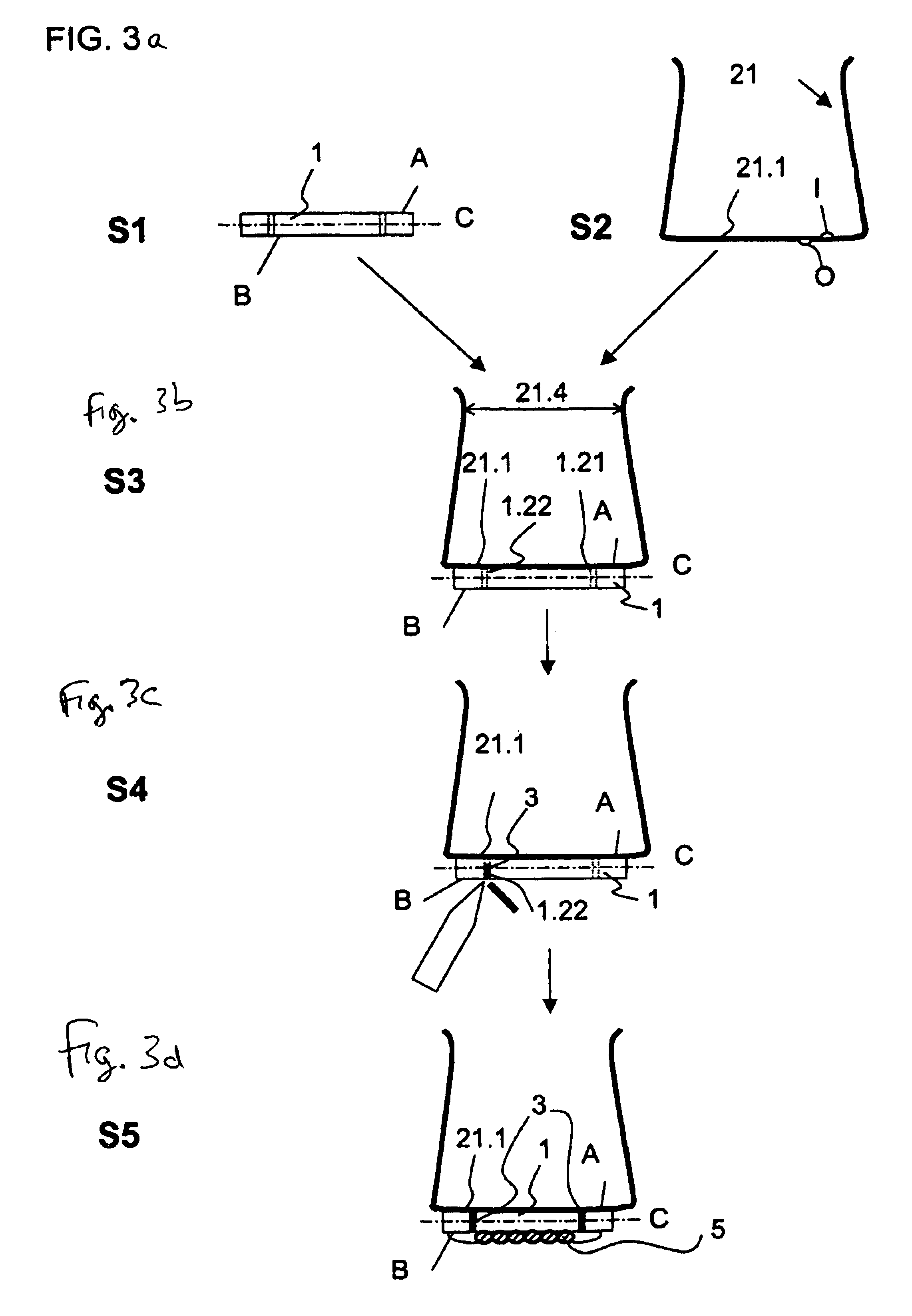
In a method for producing a slip ring brush, the slip ring brush including a brush element and a printed circuit board. The printed circuit board has a first surface and a second surface and has at least one printed circuit trace as well as at least one bore which penetrates the printed circuit board from the first surface to the second surface. An electrical contact between the brush element and the printed circuit trace is produced by soldering. The brush element is soldered such that solder penetrates from the second surface of the printed circuit board through the bore of the printed circuit board all the way to the brush element at the first surface.

Description

CROSS-REFERENCE TO RELATED APPLICATIONS[0001]The present application claims priority to Application No. 103 09 213.7, filed in the Federal Republic of Germany on Feb. 28, 2003, and to Application No. 103 24 699.1, filed in the Federal Republic of Germany on May 30, 2003, each of which is expressly incorporated herein in its entirety by reference thereto.FIELD OF THE INVENTION[0002]The present invention relates to slip ring brushes and a method for their manufacture.BACKGROUND INFORMATION[0003]Slip ring units are frequently made up of, among other things, a slip ring brush and slip rings. The slip ring brush, in operation, includes a sliding contact with rotating slip rings. Such slip ring units are used in many technical fields for transmitting electrical signals or electric power from a stationary unit to a rotating electric unit. In this context it is important that, on account of springy brush elements, there exist a good and lasting contact between the slip ring brush and the sl...

Claims


Application Information

Patent Timeline
Patent Type & Authority Patents(United States)
IPC IPC(8): H01R39/00H01R39/24H01R43/12H01R39/38
CPCH01R39/24H01R12/57Y10T29/49119H01R43/12H01R39/383
Inventor ANGERPOINTNER, LUDWIGDROST, KLAUS
Owner LTN SERVOTECHN
Why Eureka
Try Eureka