Continuous condition monitoring of transformers

a transformer and continuous condition technology, applied in the field of electrical power grids, can solve problems such as serious concerns about transformer malfunction and failur

Active Publication Date: 2010-07-29
OSLSOFT INC
View PDF15 Cites 53 Cited by
  • Summary
  • Abstract
  • Description
  • Claims
  • Application Information

AI Technical Summary

Problems solved by technology

Because transformers are a key component of electrical power grids, transformer malfunction and failure is a serious concern.
Moreover, because of significant expenses are required for aging power transformer replacements, there is a need for power transformer diagnostics to assist in the increase in power transformer lifetimes.

Method used


Image

  • Continuous condition monitoring of transformers
  • Continuous condition monitoring of transformers
  • Continuous condition monitoring of transformers

Examples


Embodiment Construction

[0014]Transformer monitoring systems can help improve reliable, efficient, and cost-effective operation of electrical grids. Automatic evaluation of on-line monitoring data can predict the onset of transformer stresses and failures. In addition, systems that include suitable diagnostic analysis can also assist in the detection of stresses on the transformer that can affect its lifetime and assist in performing condition-based maintenance.

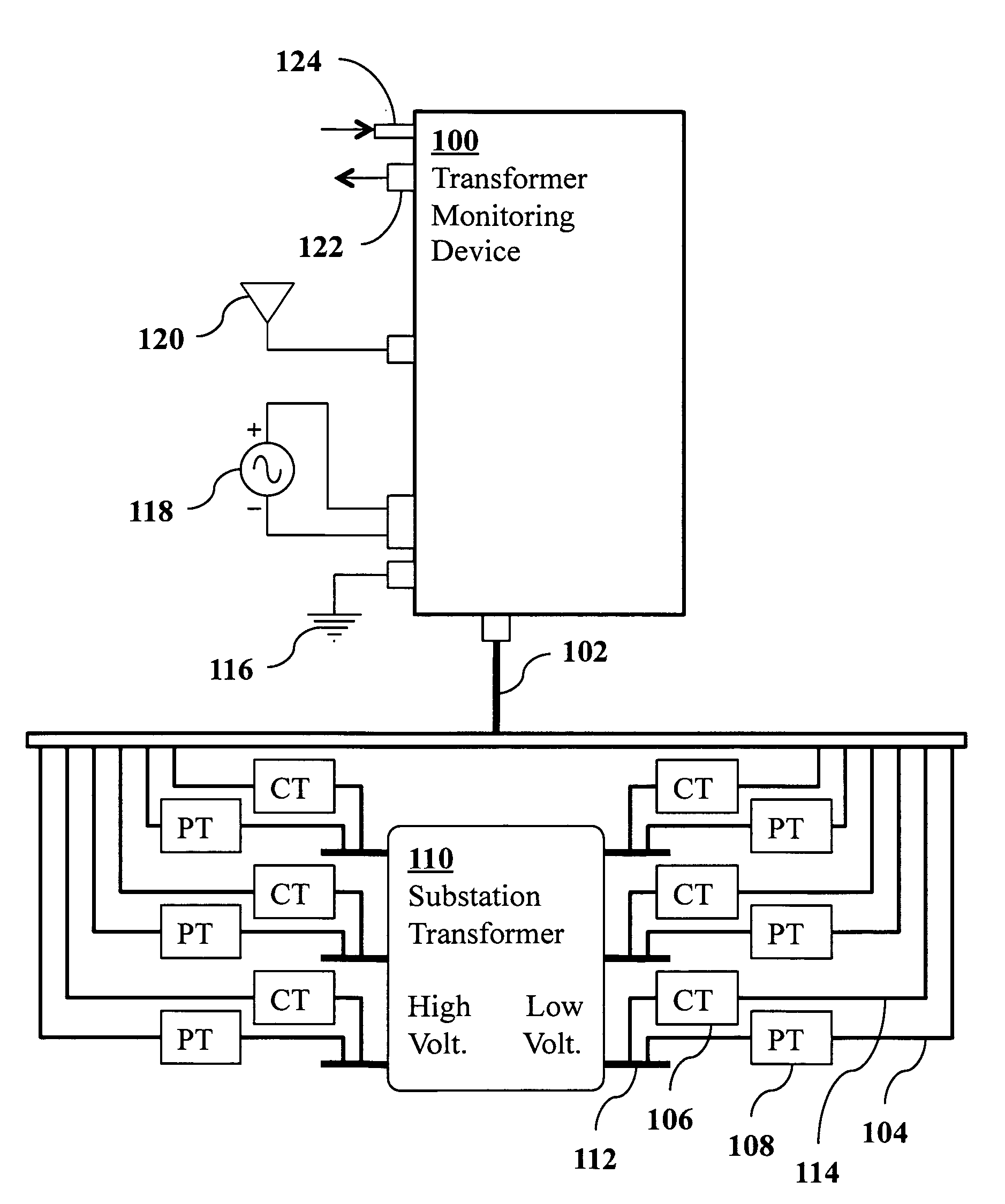
[0015]FIG. 1 is a schematic diagram of a system according to an embodiment of the invention which may be used to implement a technique for the efficient, continuous, real-time monitoring of a transformer condition using on-line impedance monitoring. The techniques may also identify and / or predict transformer malfunction or failure. A transformer condition monitoring device 100 is connected using a 36 pin Mil C 5015 connector to a prefabricated armored flex cable 102 for receiving signals from a substation transformer 110.

[0016]At the transformer, cu...


PUM


Abstract

A device and method for monitoring the condition of an electrical power transformer in an electrical power grid synchronously measures current and voltage data at both a high voltage side of the transformer and a low-voltage side of the transformer and computes from this measured data corresponding transformer impedance data. These measurements and computations are repeated continuously in real time at a rates up to 30 Hz to provide a sequence of real-time transformer impedance data. An alarm signal is generated if a mean of the sequence of real-time transformer impedance data changes significantly.

Description

CROSS-REFERENCE TO RELATED APPLICATIONS[0001]This application claims priority from U.S. Provisional Patent Application 61 / 206,398 filed Jan. 29, 2009, which is incorporated herein by reference.FIELD OF THE INVENTION[0002]The present invention relates generally to electrical power grids and the transformation of power from one voltage to another. More specifically, it relates to devices and methods for monitoring the condition of electrical power transformers in a grid.BACKGROUND OF THE INVENTION[0003]Electrical power grids include power generation stations, high-voltage transmission grids, and lower-voltage distribution grids. Step-up transformers at the generating stations provide high-voltage (over 100 kV) power to the transmission grid for efficient long-distance power transmission. Step-down transformers at distribution substations convert the high-voltage power to lower-voltage power that is distributed over shorter distances for local use. These transformers are associated wit...

Claims


Application Information

Patent Timeline
Patent Type & Authority Applications(United States)
IPC IPC(8): G08B21/00
CPCG01R31/02H02H7/045G01R31/027G01R31/62
Inventor WELLS, CHARLES H.
Owner OSLSOFT INC
Why Eureka
Try Eureka