
Image forming apparatus and display method using operation display portion thereof

Inactive Publication Date: 2010-07-29
KYOCERA DOCUMENT SOLUTIONS INC
View PDF6 Cites 5 Cited by
  • Summary
  • Abstract
  • Description
  • Claims
  • Application Information

AI Technical Summary

Benefits of technology

[0009]In view of the foregoing problem of the conventional technology, the present invention has an object to enhance the operability of an operation of searching for a transmission destination in an image forming apparatus.
[0011]Thus, it is possible to further narrow the transmission destination information by operating the second input key after the operation of the first input key. This makes it possible to narrow the transmission destination information with more detailed conditions, and enhance the operability of the operation of searching for the transmission destination information. Hence, even when the number of transmission destinations that can be stored in the address book is increased due to increased memory capacity, it is possible to enhance the searchability of the transmission destination information.

Problems solved by technology

In the conventional image forming apparatus described above, it is easy to recognize the category, but it is difficult to enhance the searchability of the transmission destination.
Disadvantageously, this complicates an operation of searching for the desired transmission destination from a large number of transmission destinations stored (registered) in the address book.
In particular, in recent years, devices that can store thousands of transmission destinations (for example, more than 2000 destinations) in an address book due to increased memory capacity have not been uncommon; in this type of device, the operation of searching for the desired transmission destination is more complicated.

Method used


Image

  • Image forming apparatus and display method using operation display portion thereof
  • Image forming apparatus and display method using operation display portion thereof
  • Image forming apparatus and display method using operation display portion thereof

Examples


Embodiment Construction

[0027]An embodiment embodying the present invention will be described in detail below with reference to the accompanying drawings. In the following embodiment, a description is given of an example of a case where the present invention is applied to a multifunction machine 1, which is an example of an image forming apparatus.

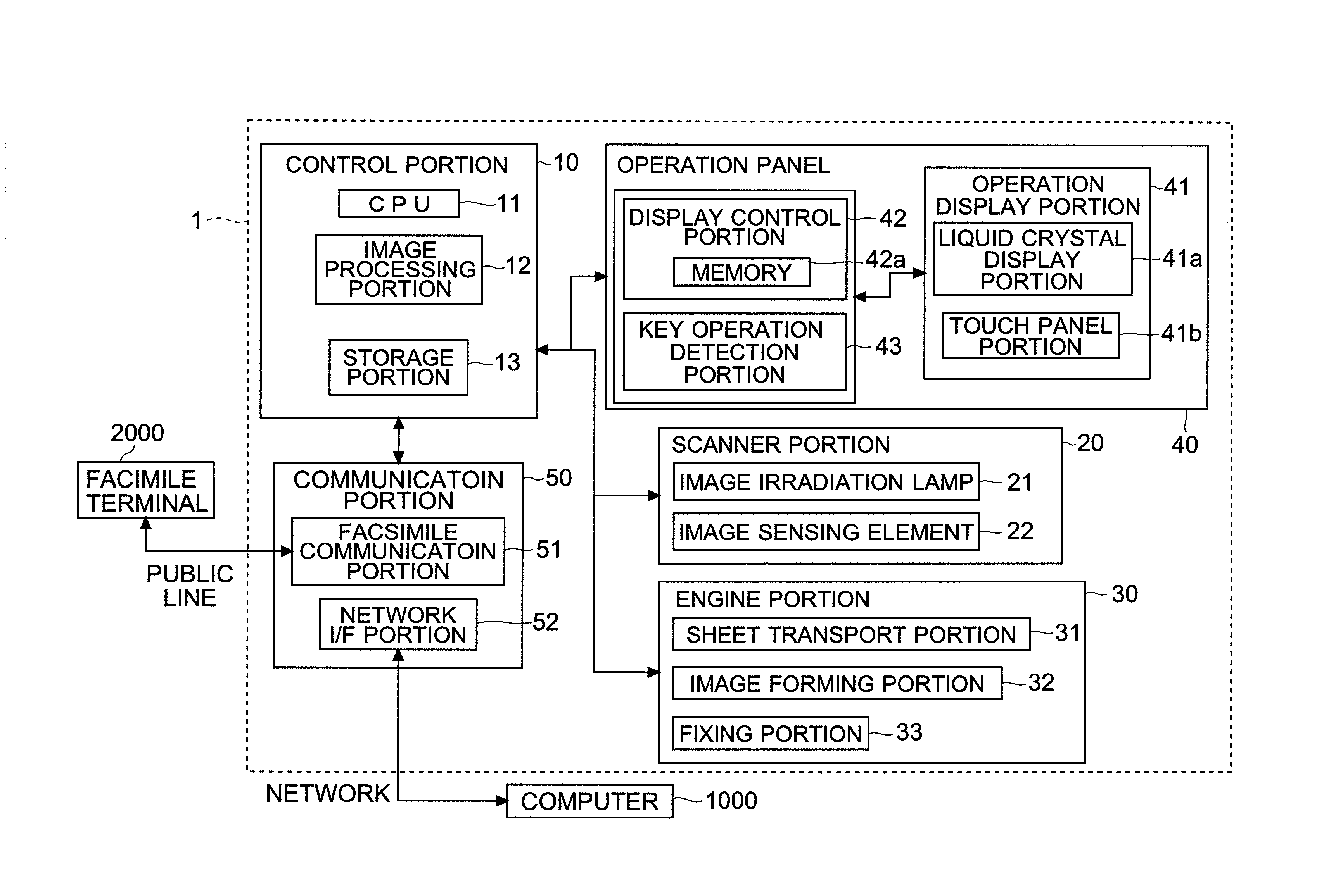
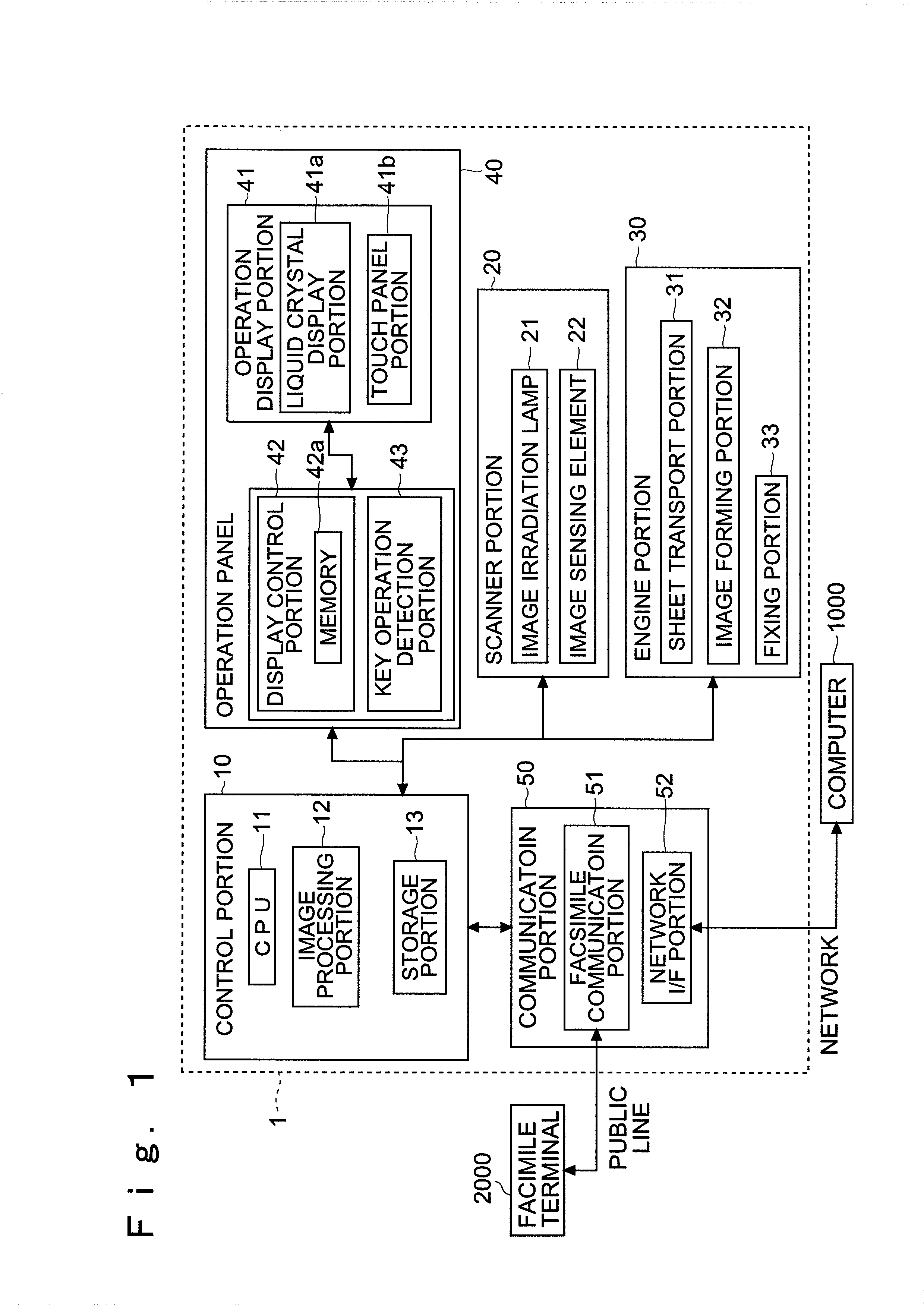
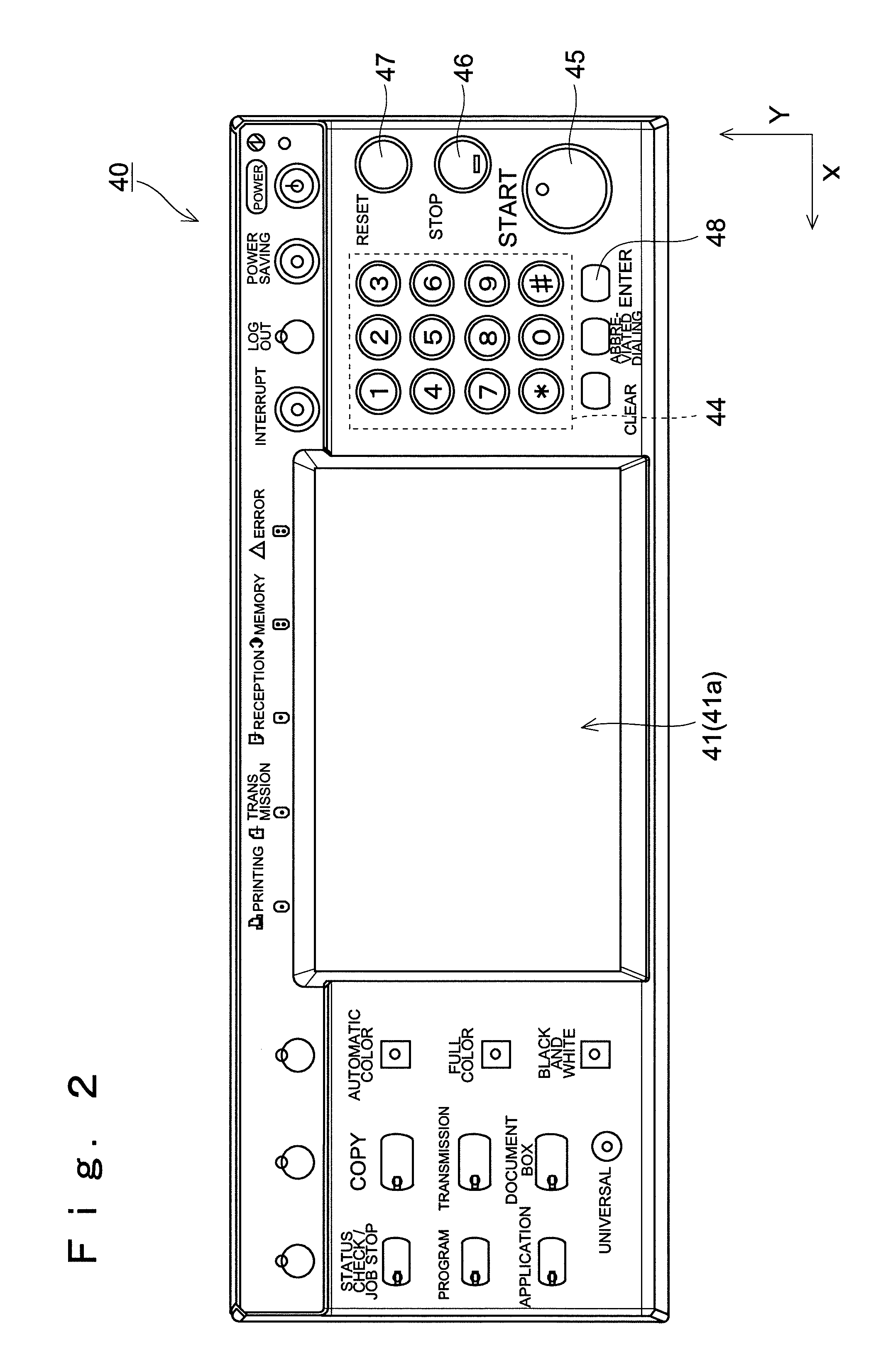
[0028]FIG. 1 is a block diagram showing an example of a schematic configuration of the multifunction machine 1 of the embodiment of the present invention. FIG. 2 is a plan view showing an example of an operation panel 40 in the multifunction machine 1 of the embodiment of the invention.

[0029](The Schematic Configuration of the Image Forming Apparatus)

[0030]The multifunction machine 1 according to the embodiment of the invention will first be schematically described with reference to FIG. 1. The multifunction machine 1 of this embodiment is a network-compatible digital multifunction machine 1 that has functions such as a scanner function, a printer function, a cop...


PUM


Abstract

An image forming apparatus includes: a communication portion; an operation display portion that displays at least an address book screen on which a plurality of first input keys for narrowing transmission destination information are displayed, on which the first input key is operated such that a plurality of second input keys for further narrowing the transmission destination information are displayed and on which the displayed second input key is operated such that the transmission destination information is narrowed and the resulting information is displayed along with names; a display control portion that controls a display on the operation display portion; a key operation detection portion that detects a key operation on the input keys including the first input keys and the second input keys; and a storage portion that stores a plurality of pieces of transmission destination information displayed on the address book screen such that the plurality of pieces of transmission destination information correspond to names, respectively.

Description

[0001]This application is based on and claims the benefit of priority from the corresponding Japanese Patent Application Nos. 2009-013791 and 2009-013793 filed on Jan. 26, 2009, the contents of which are hereby incorporated by reference.BACKGROUND OF THE INVENTION[0002]1. Field of the Invention[0003]The present invention relates to an image forming apparatus such as a multifunction machine, a copying machine, a printer or a facsimile, and more particularly to an image forming apparatus that has a transmission function.[0004]2. Description of Related Art[0005]In recent years, image forming apparatuses (multifunction machines) having functions such as a scanner function, a printer function, a copying machine function and a facsimile function have been widely used. These image forming apparatuses have not only the function of forming an image but also the function of transmitting various types of data through a telephone line, a network or the like.[0006]In this type of image forming a...

Claims


Application Information

Patent Timeline
IPC IPC(8): G06F15/00
CPCG06F3/0482G06F3/04886H04N1/00405H04N1/00411H04N2201/0094H04N1/00472H04N1/00474H04N1/32058H04N1/00413
Inventor MAEDA, TETSUYASEKIGUCHI, YASUHIRO
Owner KYOCERA DOCUMENT SOLUTIONS INC
Learn More