Disk implant

a technology of implant and stent, which is applied in the field of stent, can solve the problems that other requirements and conditions cannot be met, and achieve the effects of reliable transfer of chewing force, long-lasting secure seating of implants, and reliable prevention of separate crown rotation

Inactive Publication Date: 2010-07-29
BIOMED EST
View PDF6 Cites 0 Cited by
  • Summary
  • Abstract
  • Description
  • Claims
  • Application Information

AI Technical Summary

Benefits of technology

[0014]The outer surface of the abutment also has at least one rotational stop, which can for instance be in the form of a flat or a flat side, which interacts with a corresponding mating part in the mounting hole of an attachment and reliably prevents separate rotation of the crown or other kind of tooth replacement placed on the abutment above the attachment.
[0015]Aside from the increased contact area of the implant foot on the corticalis, which results advantageously in long-lasting secure seating of the implant and the reliable transfer of the chewing forces into the jaw bone, the solution according to the invention and the firm contact of the shaft in the vertical portion of the implant bed achieve high primary stability, as both the implant foot and the vertical part of the implant, i.e., the shaft, is in firm contact in the implant bed of the jaw bone. That was not possible with the previously known solutions for the design of the implant foot and shaft of a disk implant.

Problems solved by technology

These and other requirements and conditions cannot be met by disk implants in which the implant foot is designed uniformly throughout.

Method used


Image

  • Disk implant
  • Disk implant

Examples


Embodiment Construction

[0023]The following description of the preferred embodiment(s) is merely exemplary in nature and is in no way intended to limit the invention, its application, or uses.

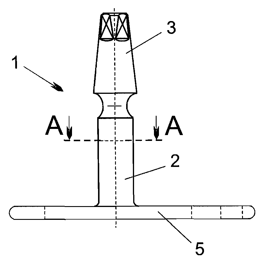
[0024]As can be seen from FIG. 1, the disk implant has a generally known design, comprising the implant foot 5 and the implant shaft 2, which is firmly connected with the implant foot 5 through the bar 4, and which is arranged orthogonally to the implant foot 5, and which has at its tip an abutment 3 to accept and fasten a crown or the attaching art of a tooth replacement.

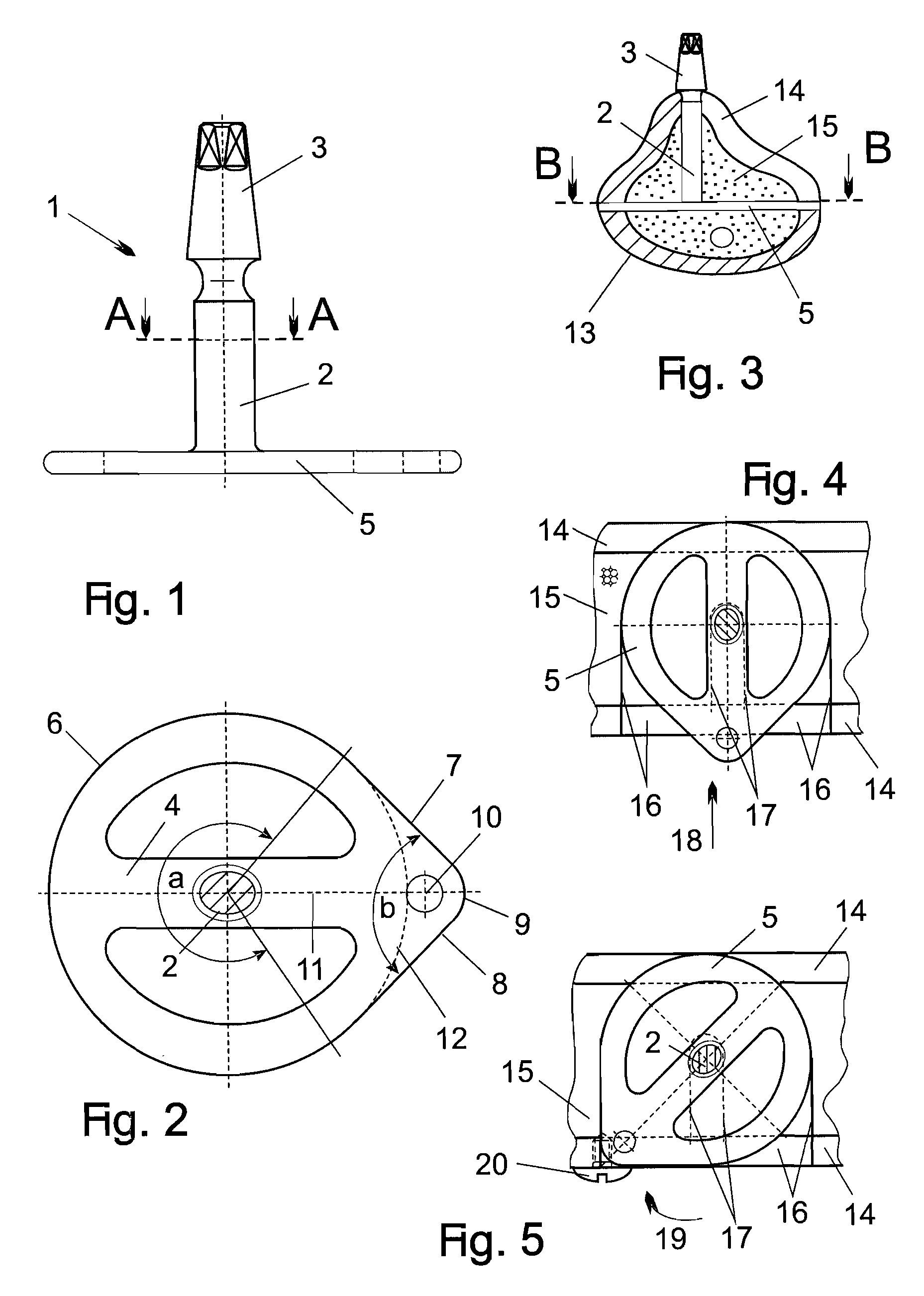
[0025]According to the invention, the foot section 6 of the implant foot 5 has a circular outline with a diameter approximately corresponding to the diameter of the grinding tool used to produce the implant bed 16, extending around an arc a of 260° to 280°—FIG. 2. Two long sides, 7 and 8, attach to this circular outline. They are arranged symmetrically with respect to the central axis 11 of the implant foot 5, and their ends, which extend beyond the ...


PUM


Abstract

A dental implant for mounting prosthetic devices such as crowns, comprising a shaft having an external end adapted for receiving a prosthetic device, a foot attached to an opposing end of the shaft, the foot and shaft being generally orthogonal and the implant foot having a circular outline over an arc α with two long substantially linear sides enclosing an angle β, the linear sides being disposed substantially symmetrically with respect to the shaft.

Description

BACKGROUND OF THE INVENTION[0001]1. Field of the Invention[0002]The present invention concerns a disk implant that is anchored in the jawbone by basal osseointegration and serves to accept and hold a tooth replacement or a crown.[0003]Quite different solutions have been suggested in the past for the design and structure of the implant foot for disk implants, through which the implant is anchored in the jawbone by basal osseointegration and through which the chewing forces taken up by the implant are transferred into the jawbone.[0004]2. Related Art[0005]There are implants with an implant foot that is approximately square to rectangular, DE 299 17 858.7 or DE 3 018 255, and implants the foot part of which is made up of a round disk, or a multiplicity of round disks with the same or different diameters stacked vertically, as in DE 199 48 910 A1 and EP 0 935 949 B1. Implants are also known that have an implant foot comprised of two adjacent rings, EP 1 050 282 B1, and implants in which...

Claims


Application Information

Patent Timeline
Patent Type & Authority Applications(United States)
IPC IPC(8): A61C8/00
CPCA61C8/001
Inventor IHDE, STEFAN
Owner BIOMED EST
Why Eureka
Try Eureka