Intervertebral implant for the fusion between two vertebral bodies of a vertebral column and corresponding positioning instrument

a technology of intervertebral implants and vertebral bodies, which is applied in the field of intervertebral implants for fusion between vertebral bodies of vertebral columns, can solve the problems of inability to engage the instrument in-situ, the instrument cannot allow angular adjustment of the implant with respect to the instrument, and the working steps are not simplified compared to a simple thread. , to achieve the effect of simple operation procedure, simple structure and high primary stability

Active Publication Date: 2012-11-01
MEDACTA INT SA
View PDF6 Cites 102 Cited by
  • Summary
  • Abstract
  • Description
  • Claims
  • Application Information

AI Technical Summary

Benefits of technology

[0012]An object is to provide an implant with high primary stability and that allows a simple operative procedure in use.
[0013]An object is to provide an implant with a simple structure and low cost.
[0014]An implant for the fusion between two vertebral bodies of a vertebral column may include an engagement portion for receiving a gripping end of a positioning instrument. This may allow a very strong and stable gripping of such a gripping end thanks to a particular shape of the engagement portion.

Problems solved by technology

The implant instrument locking is done by a thread member that, however, does not simplify the working steps compared to a simple thread.
In case of a 90° locking, less manipulation steps may be required, but the instrument does not allow angularly adjustment of the implant with respect to the instrument.
This approach has a complex instrument locking mechanism instead of a 90° lock / unlock mechanism and it's impossible to engage the instrument in-situ.
The implant fixation is done with a linear movement of the sleeve, but this linear movement can cause tissue damage and it is not as simple as a 90° locking.
It is impossible to engage the instrument is-situ.
The engagement / disengagement mechanism may be inferior compared to a 90° locking mechanism because of its complexity.
The interface is a friction lock, which has reduced stability compared to a positive lock.
The engagement / disengagement mechanism may be less desirable as compared to a 90° locking mechanism because of the required working steps.
The interface is a friction lock, which has reduced stability as compared to a positive lock.
In addition, in-situ engagement is not possible due to the thread.
The fixation of the implant to the instrument is more difficult compared to a 90° locking instrument.

Method used


Image

  • Intervertebral implant for the fusion between two vertebral bodies of a vertebral column and corresponding positioning instrument
  • Intervertebral implant for the fusion between two vertebral bodies of a vertebral column and corresponding positioning instrument
  • Intervertebral implant for the fusion between two vertebral bodies of a vertebral column and corresponding positioning instrument

Examples


Embodiment Construction

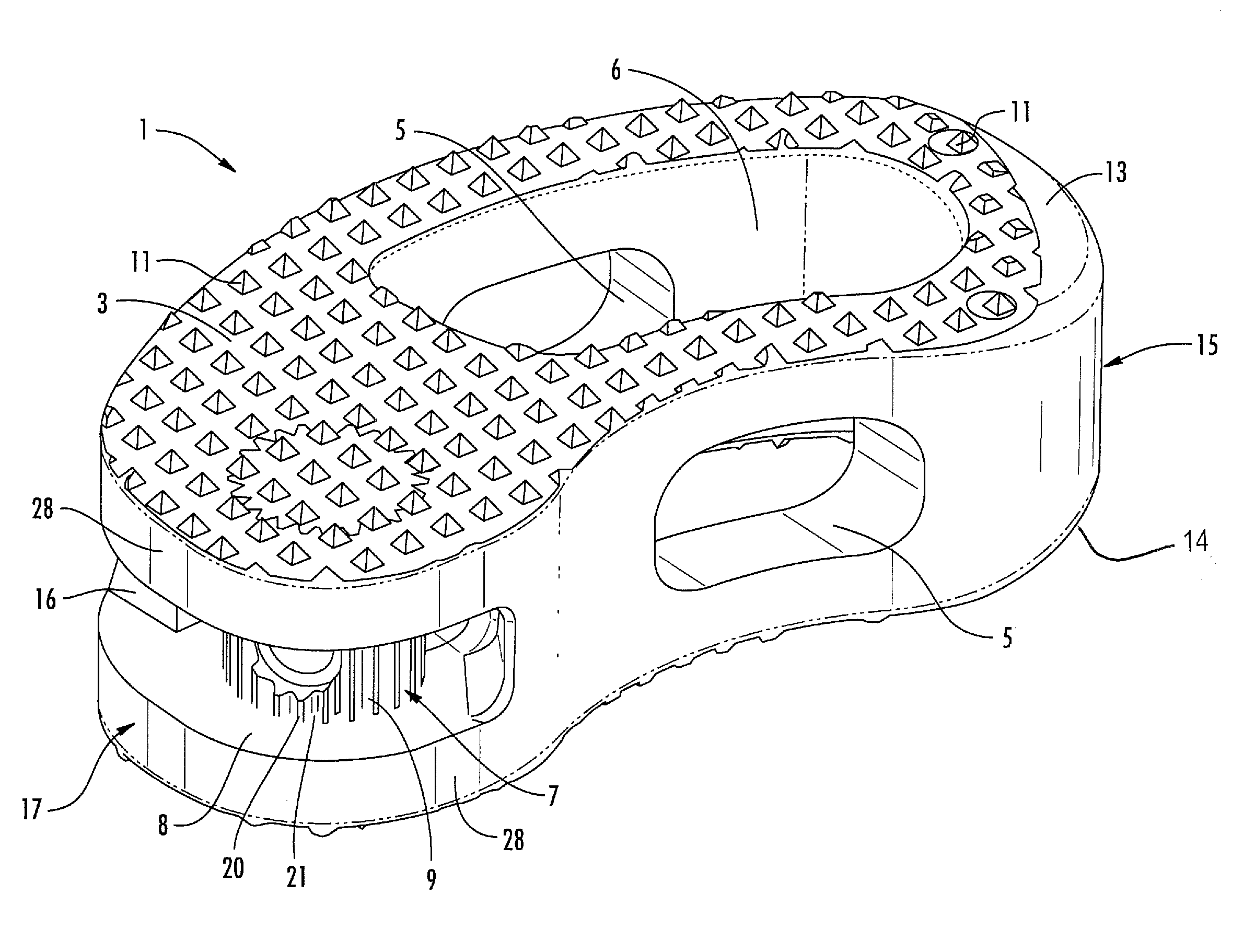
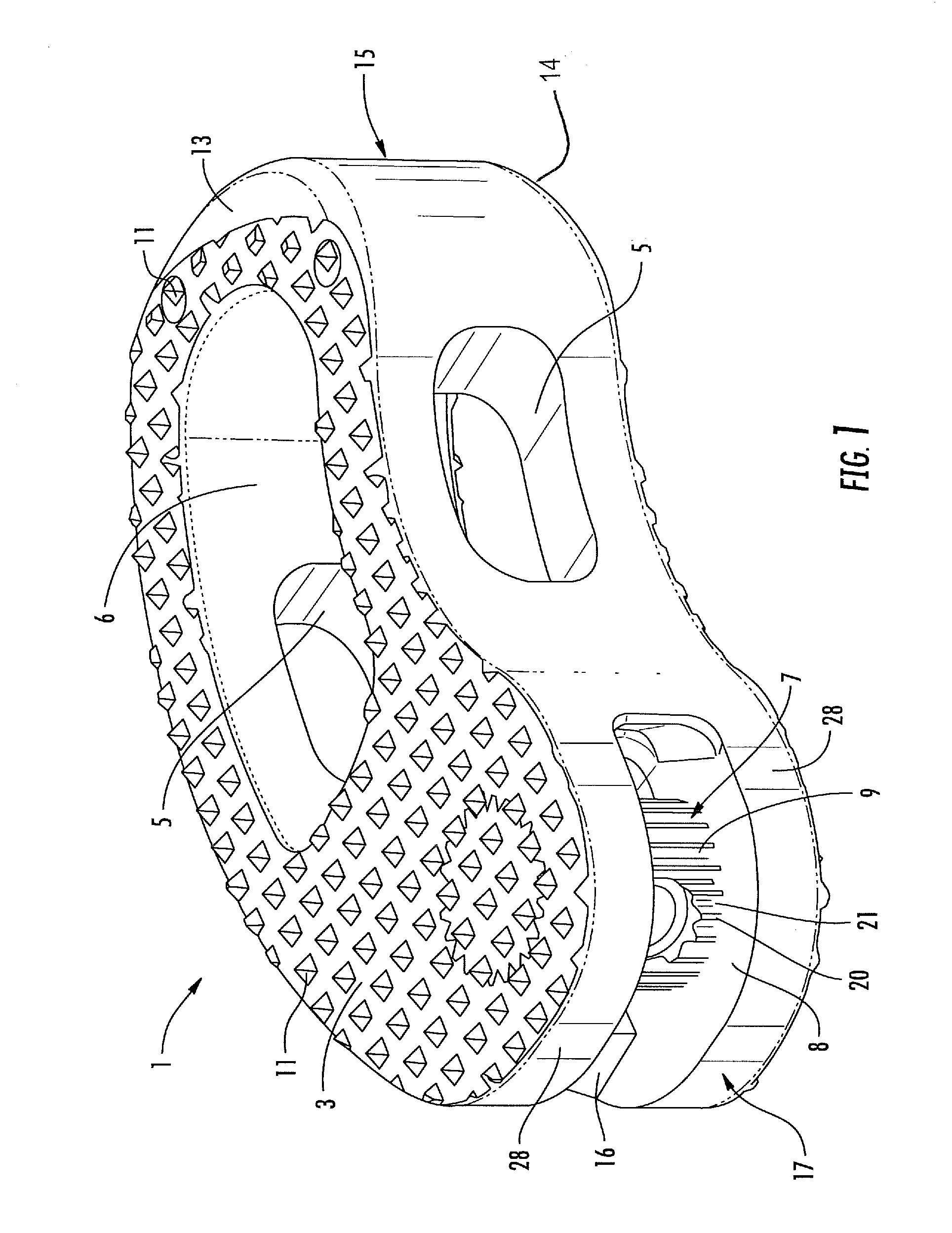
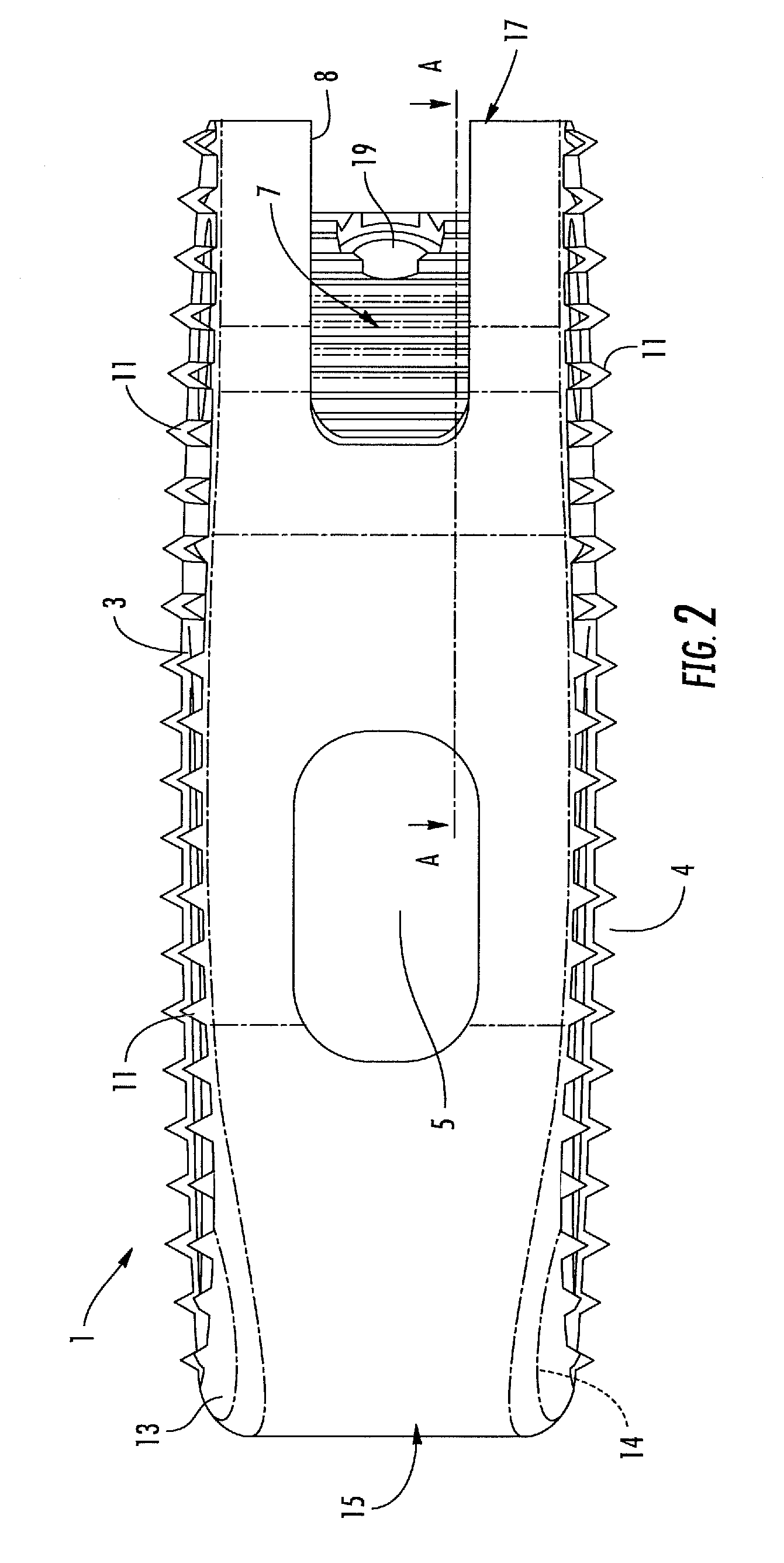
[0038]With reference to the figures, an intervertebral implant realized according to the present invention permits the fusion between two vertebral bodies of a vertebral column. The implant 1 is specifically intended to be used as an intervertebral body fusion device. The implant 1 has been specifically realized for allowing vertebral operations according to the requirement of the modern Minimally Invasive Surgery. The implant 1 is mainly dedicated to the use in TLIF (Transforaminal Lumbar Intervertebral Fusion) surgery, however, nothing prevents that it may be adopted in other surgery techniques, such as PLIF or OILF.

[0039]The implant 1 has a main body 2 realized with a biocompatible radiolucent synthetic material, for example, a Polyetheretherketone (PEEK) structure having a favorable modulus of elasticity. However, other appropriate implant materials are usable as well, for example, with or without a titanium coating.

[0040]The body 2 is Kidney-bead shaped and available in several...


PUM


Abstract

An intervertebral implant for the fusion between two vertebral bodies of a vertebral column may include a body having two opposite surfaces and holes or cavities for filling purposes during bone growth, and an engagement portion for receiving a gripping end of a positioning instrument. The engagement portion may be shaped as a splined shaft accessible through an opening of the body.

Description

FIELD OF THE INVENTION[0001]The present invention relates to an intervertebral implant for fusion between vertebral bodies of a vertebral column, and in particular, to an implant for the Transforaminal Interbody Fusion (TLIF) of lumbar vertebral column segments.BACKGROUND OF THE INVENTION[0002]As is known in this technical field, various attempts have been made to use minimally invasive surgery for spine operations. In this respect, so-called PLIF (Posterior Lateral Interbody Fusion) operation techniques have been developed. According to such an operation technique, the intervertebral disc is removed through a posterior access and an intervertebral space is filled with autologous bone.[0003]Further developments of this PLIF technique resulted in the application of a so-called TLIF operation technique based on a transforaminal access. This technique provides for the dorsal transforaminal introduction of titanium cups (so-called cages), which are filled with autologous bone. At the sa...

Claims


Application Information

Patent Timeline
Patent Type & Authority Applications(United States)
IPC IPC(8): A61F2/44
CPCA61F2/4465A61F2250/0098A61F2002/2835A61F2002/30112A61F2002/30133A61F2002/302A61F2002/30538A61F2002/30594A61F2002/30777A61F2002/30779A61F2002/30841A61F2002/4622A61F2230/0004A61F2230/0015A61F2230/0065A61F2250/0006A61F2/4611
Inventor SICCARDI, FRANCESCOFIECHTER, MEINRADJESZENSZKY, DEZSOFEKETE, ZSOLTHEYDE, CHRISTOPH E.
Owner MEDACTA INT SA
Why Eureka
Try Eureka