Fixation device and method

Inactive Publication Date: 2010-07-29
STOUT MEDICAL GROUP
View PDF4 Cites 221 Cited by
  • Summary
  • Abstract
  • Description
  • Claims
  • Application Information

AI Technical Summary

Benefits of technology

[0010]The device can be less invasive than typical existing devices. For example, the device can be in a compacted (i.e., small) configuration when inserted into a patient and transformed into an expanded (i.e., large) configuration when positioned at the target site. For example, the device can be expanded when the device is between

Problems solved by technology

Other ailments of the spine result in degeneration of the spinal disc in the intervertebral space between the vertebral bodies.
In either case, disc degeneration can cause pain and other

Method used


Image

  • Fixation device and method
  • Fixation device and method
  • Fixation device and method

Examples


Example

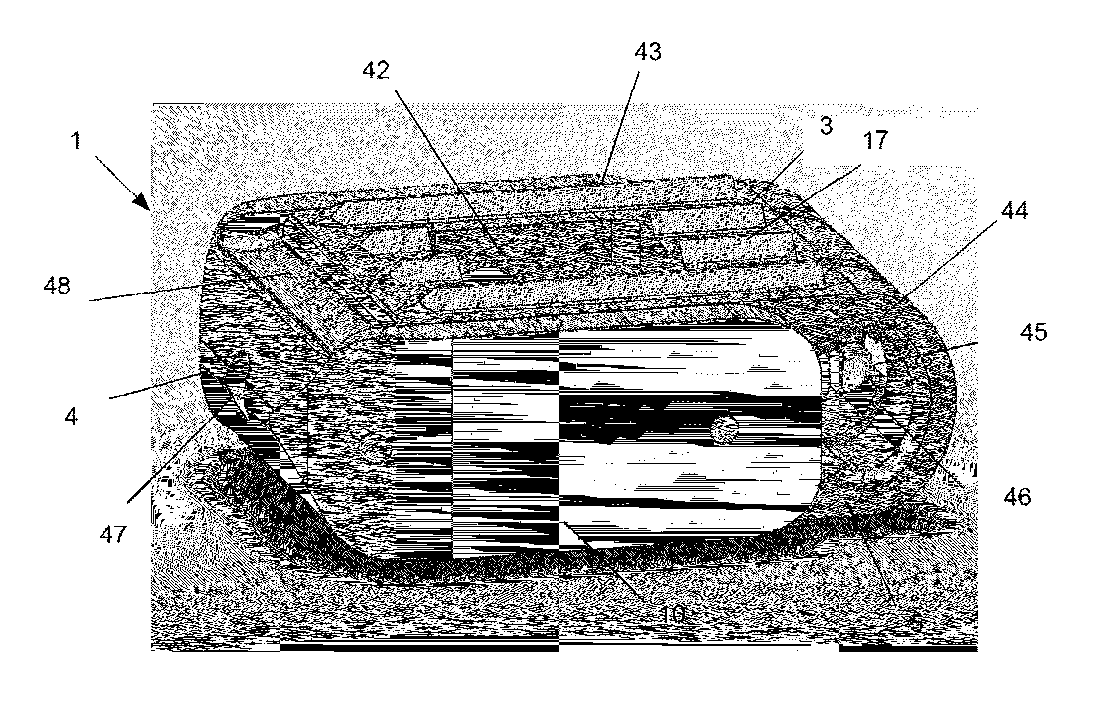
[0027]A device 1 is disclosed that can be inserted into a target site 73 with the device 1 in a compressed or contracted (i.e., small) configuration. Once positioned in the deployment site, the device 1 can be transformed into an expanded (i.e., larger, bigger) configuration. The device 1 can be inserted and expanded in orthopedic target sites 73 for fixation and / or support. For example, the device 1 can be inserted and expanded over a guidewire between adjacent vertebral facet surfaces (i.e., within a facet joint 55).

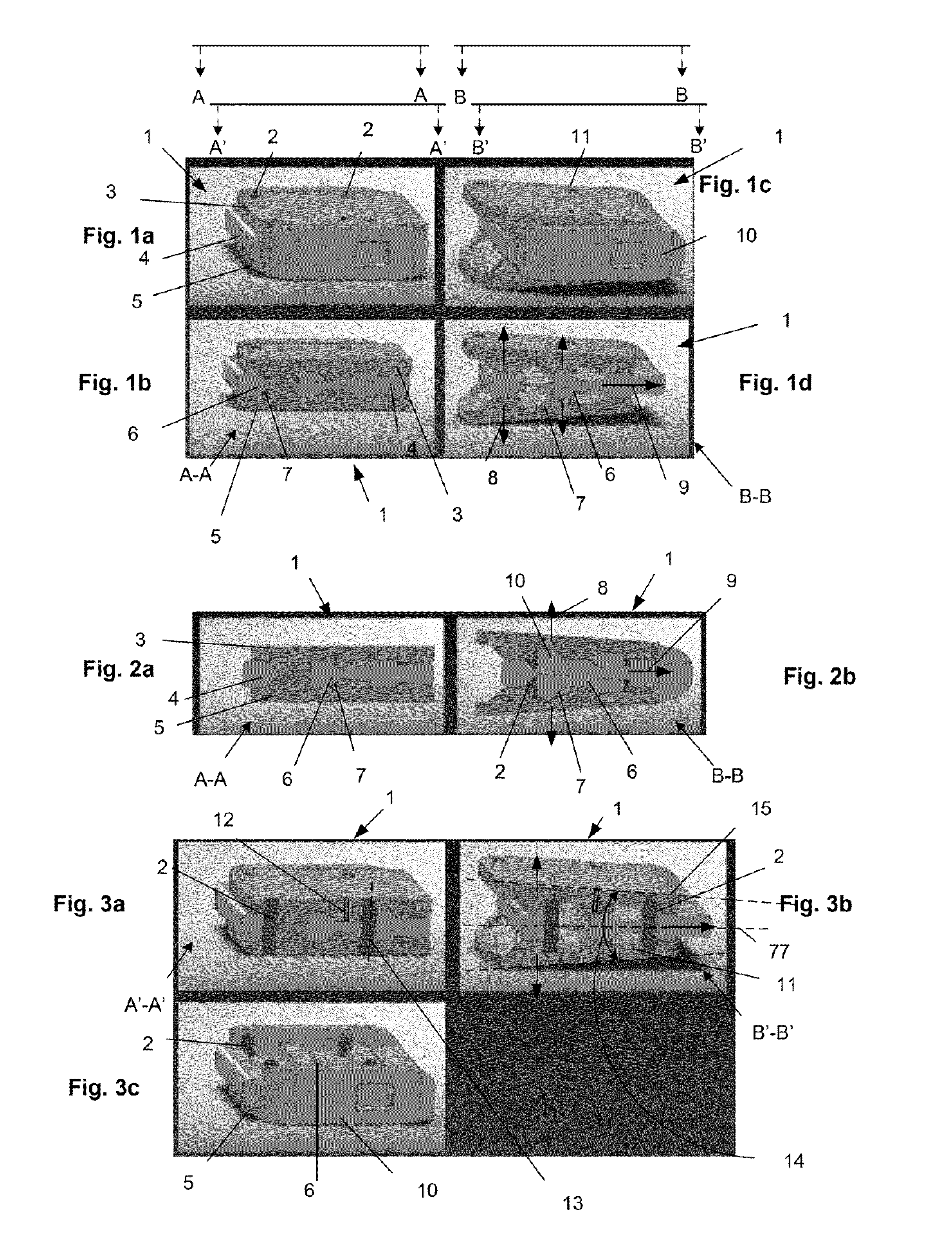
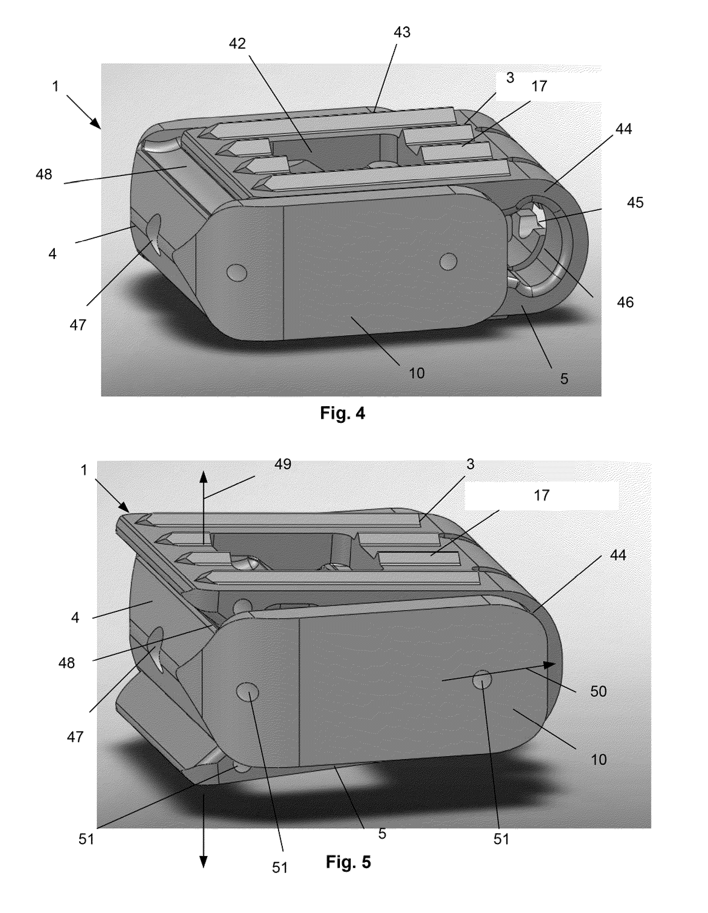
[0028]FIGS. 1a through 3c illustrate that the device 1 can have a top plate 3 attached to a bottom plate 5. The top plate 3 can be attached to the bottom plate 5 by one, two, three four or more pins 2. The plates can have a substantially flat external surface facing outward from the device 1. The pin longitudinal axes 13 can be substantially perpendicular to the plate surface planes of the external surfaces of the top 3 and bottom 5 plates when the device 1 is in a con...


PUM

PropertyMeasurementUnit
Angleaaaaaaaaaa
Angleaaaaaaaaaa

Abstract

An implantable orthopedic stability device is disclosed. The device can have a contracted and an expanded configuration. A method of using the device between adjacent vertebral surfaces for support and/or fixation of either or both of the adjacent vertebrae is also disclosed.

Description

CROSS-REFERENCE TO RELATED APPLICATIONS[0001]This application is a continuation-in-part of U.S. patent application Ser. No. 12 / 617,663, filed Nov. 12, 2009; and Ser. No. 12 / 617,526, filed Nov. 12, 2009, which claim the benefit of U.S. Patent Application No. 61 / 113,691, filed on Nov. 12, 2008.BACKGROUND OF THE INVENTION[0002]1. Technical field[0003]Devices and methods for fixation of tissue are disclosed. More specifically, the devices and methods can be for inter facet fusion of vertebrae or fusion of other bones to one another.[0004]2. Background of the Art[0005]A vertebroplasty device and method that eliminates or reduces the risks and complexity of the existing art is desired. A vertebroplasty device and method that may reduce or eliminate the need to inject a liquid directly into the compression fracture zone is also desired.[0006]Other ailments of the spine result in degeneration of the spinal disc in the intervertebral space between the vertebral bodies. These include degenera...

Claims


Application Information

Patent Timeline
IPC IPC(8): A61F2/44
CPCA61F2/4455A61F2310/00976A61F2002/3008A61F2002/30471A61F2002/30492A61F2002/305A61F2002/30522A61F2002/30538A61F2002/30579A61F2002/30594A61F2002/4677A61F2210/0004A61F2220/0025A61F2220/0091A61F2250/0006A61F2250/0098A61F2310/00017A61F2310/00023A61F2310/00029A61F2310/00101A61F2310/00137A61F2310/00796A61F2310/00952A61F2310/0097A61F2002/30062
Inventor GREENHALGH, E. SKOTT
Owner STOUT MEDICAL GROUP
Why Eureka
Try Eureka