

Methods, apparatus and system for use in dental procedures
a technology for dental procedures and instruments, applied in the field of dental data and dental procedures, can solve the problems of time-consuming and complicated process, requiring expert handling, etc., and achieve the effect of facilitating said determination
- Summary
- Abstract
- Description
- Claims
- Application Information
AI Technical Summary
Problems solved by technology
Method used
Image

Examples
first embodiment
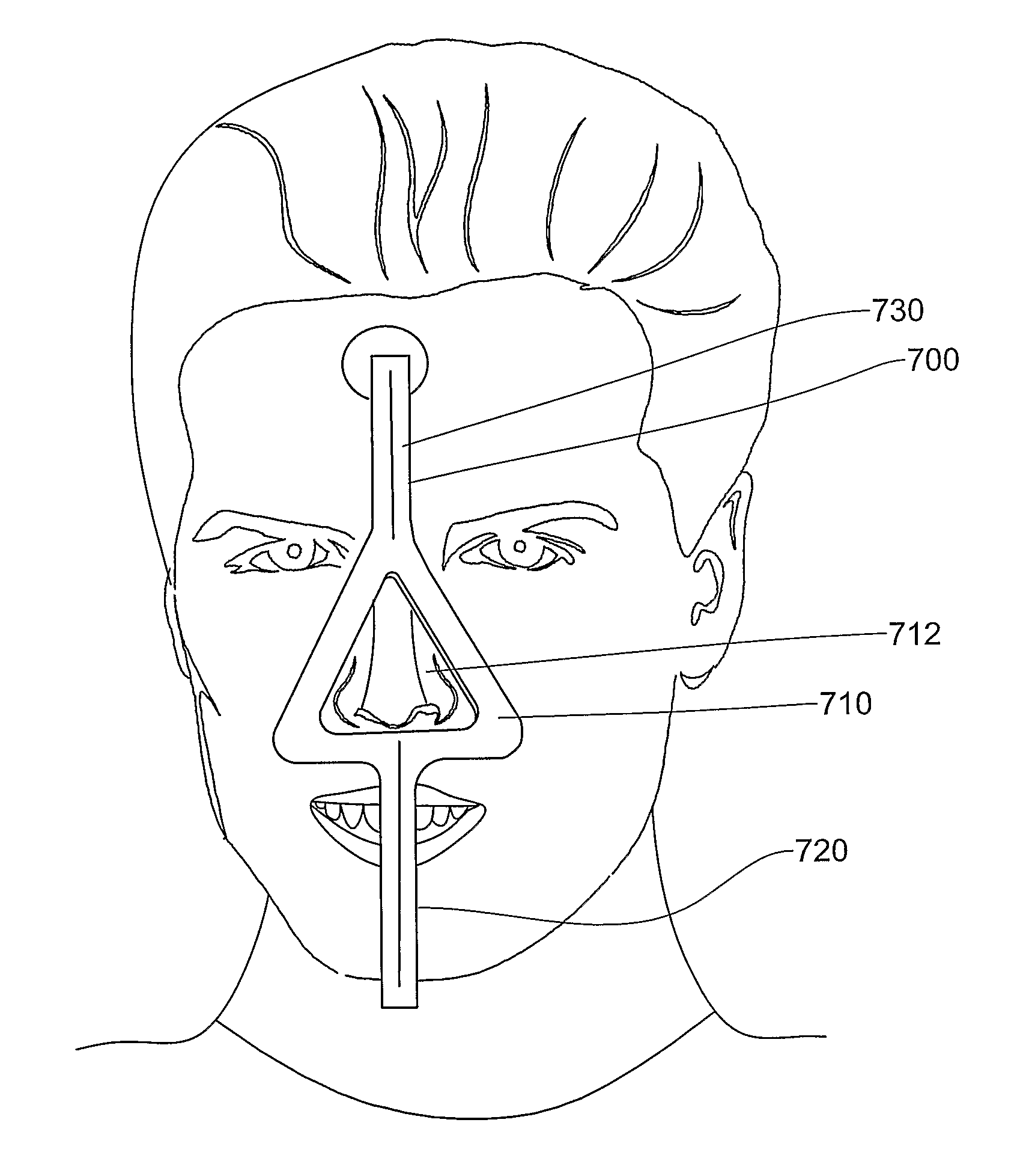
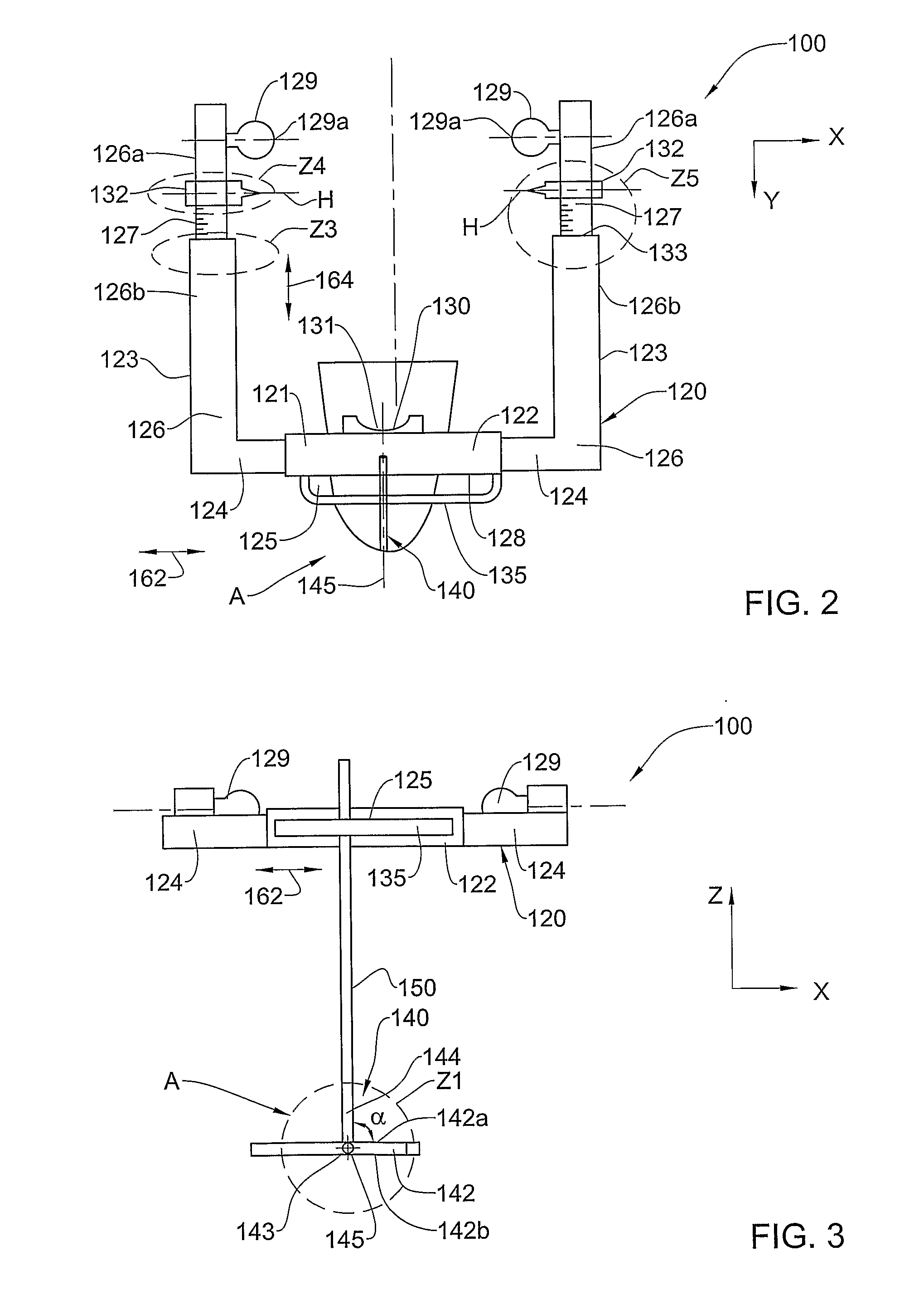
[0138]The facebow apparatus is configured for providing sufficient spatial information for defining the position of the dental arches of a patient in three-dimensions with respect to the hinge axis of the patient's jaw. Referring to FIGS. 2 to 4, a facebow apparatus according to the invention, which is per se novel, is generally designated with reference numeral 100, and comprises a facebow portion 120 and a bite fork portion 140.
[0139]The facebow portion 120 is in the form of a U-shaped member adjustable in two, generally orthogonal directions, enabling this component to be fitted to a range of patients having widely differing anatomies.
[0140]The facebow portion 120 comprises a pair of L-shaped arms 123, each comprising a first member 124 joined to a second member 126 at an angle thereto, typically orthogonal, though in alternative embodiments may be acute or obtuse, the first member 124 being telescopically movable with respect to a common central member 122 in a controllable mann...
second embodiment
[0231]In alternative variations of the second embodiment, rather than the bite fork portion 140, any suitable rigid plate, strip, rod, or the like may be aligned with the midsagittal plane of the patient, in close visual proximity to the intraoral cavity, so that a portion of the thus vertical plate is visually coupled to a portion of the teeth during a scanning thereof in step 430, sufficient for enabling reconstruction of the vertical surface of the plate and of enough of the dental surface to allow a match in step 450 with the first virtual model to be achieved.
[0232]In yet other variations of this embodiment, any suitable geometrical structure, for example in the form of an artifact, may be coupled to a portion of the teeth during a scanning thereof in step 430, sufficient for enabling reconstruction of the geometrical structure and of enough of the dental structure to allow a match in step 450 with the first virtual model to be achieved. The geometrical structure can comprise a...
third embodiment
[0247]In the invention, in step 430 external tissue structures, not included in the intraoral cavity, may be scanned, while visually coupled to at least a portion of the dental surfaces of the patient. For example, and referring to FIG. 8 (b), the lips, or at least the upper lip 380 of the patient is scanned together with part of the dental structure 385 visually coupled therewith, and a second virtual model of the lip 380 and dental structure 385 is reconstructed. The lips may be in a smiling position when the scan is taken. Another scan is taken to establish the first virtual model of the dental surfaces of the intraoral cavity, which also include representations of the same dental structure 385 that appear in the scan illustrated in FIG. 8(b), as well as a number of incisor teeth 386 which need crowns. According to this embodiment, the first and second virtual models are combined by registering the respective parts thereof corresponding to common dental structure 385, and the pro...
PUM
 Abstract
Description
Claims
Application Information