Fully automatic coupler for excavator arm

a fully automatic, coupler technology, applied in the direction of mechanical machines/dredgers, soil shifting machines/dredgers, agricultural undercarriages, etc., can solve the problems of not only the operator, but also the bystander, the accessory might not be fully and securely fastened to the coupler, and the inability to use it incorrectly, so as to achieve enhanced resistance to the opening of the first latching member

Active Publication Date: 2010-08-05
MILLER INT
View PDF13 Cites 25 Cited by
  • Summary
  • Abstract
  • Description
  • Claims
  • Application Information

AI Technical Summary

Benefits of technology

[0044]Preferably the latching member of the first latching mechanism has a face that is adapted to face towards an attachment pin of an accessory, when the accessory pin is located fully within the front jaw. Preferably that surface extends downwardly into the jaw at least one-third of the way across the opening. More preferably it extends at least halfway across the opening. By extending it sufficiently across the opening, and / or providing it with an appropriate shape, an attachment pin in the front jaw can usually be prevented from forcing the first latching mechanism from its jaw-closing position into its open position, even if the pin was to apply a considerable force against the latching member.
[0045]The resistance to opening of the first latching member can be enhanced further by correctly locating the hinge axis of the first latching member above the line of reaction force between the attachment pin and the pin facing / engaging surface of the latching member as will occur once the first latching member is in its jaw-closing position. With that arrangement, those reaction forces would tend to maintain the latching member in a closed position, rather than tending to open the jaw.

Problems solved by technology

With any coupler, it is possible to use them incorrectly.
Therefore it is possible that an accessory might not be fully, and securely, fastened onto the coupler.
Such situations can lead to dangers, not only for the operator, but also for bystanders.
That is because such an incorrectly mounted accessory can potentially fall off the coupler if the error is not noted and corrected.

Method used


Image

  • Fully automatic coupler for excavator arm
  • Fully automatic coupler for excavator arm
  • Fully automatic coupler for excavator arm

Examples


Embodiment Construction

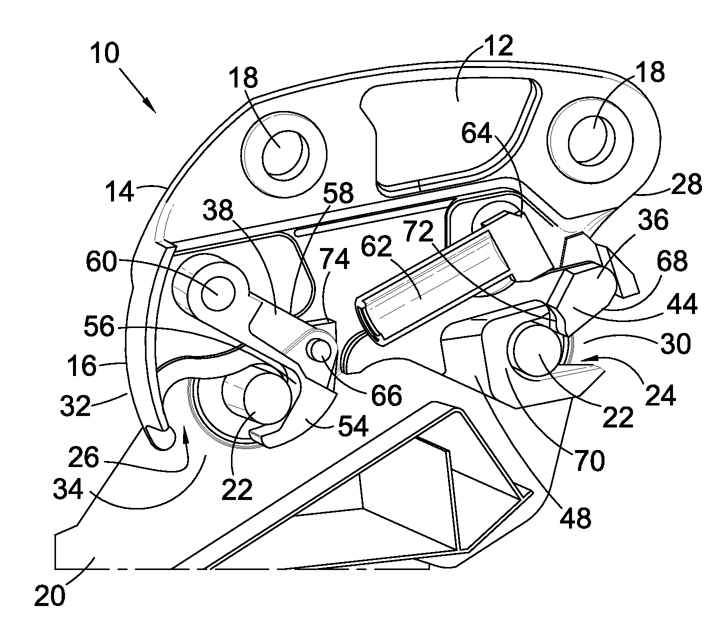
[0089]Referring first of all to FIG. 1, there is shown a partial section through a coupler of the present invention. Various internal elements of the coupler have been simplified or removed for clarity. What is illustrated, however, is a coupler 10 comprising a frame 12 having a top half 14 and a bottom half 16.

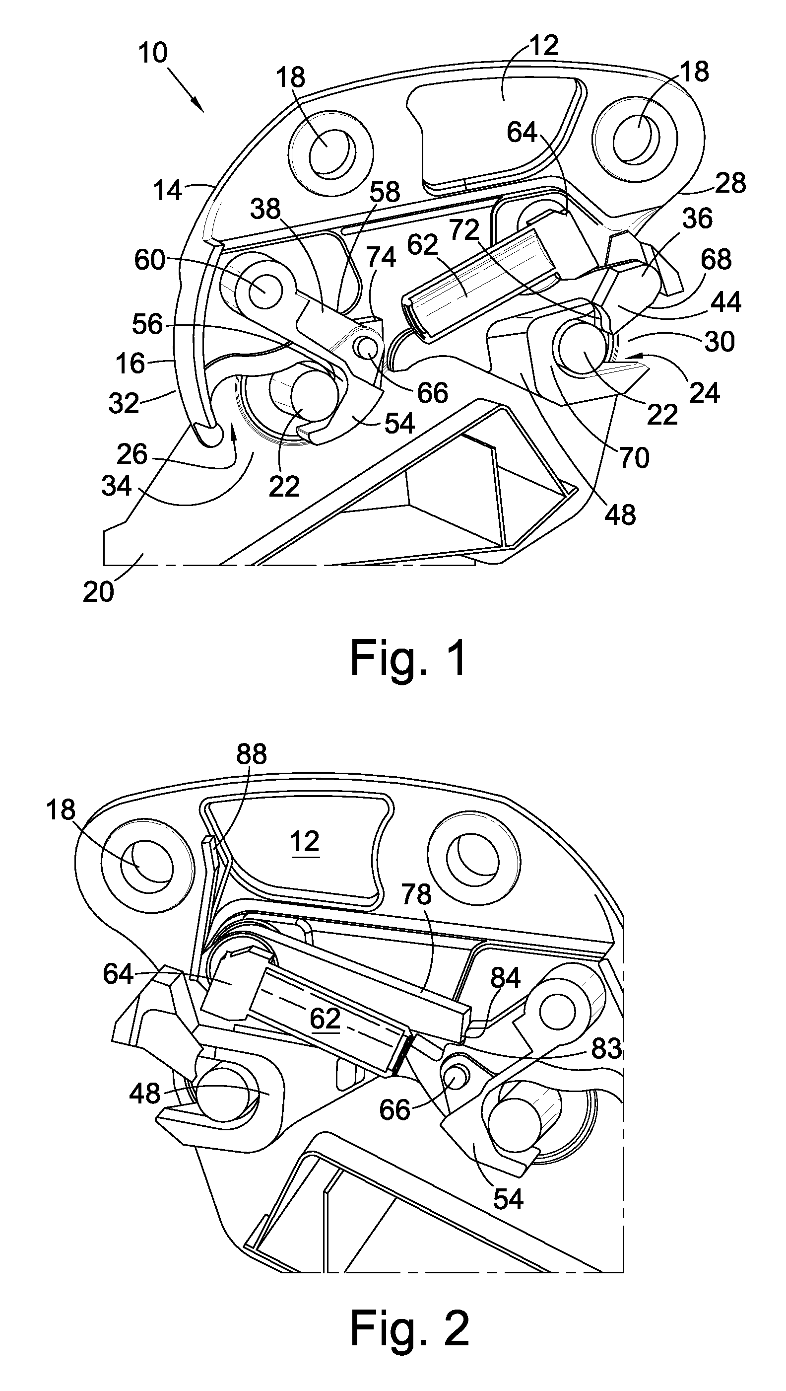
[0090]The opposite side of the coupler 10 is shown in FIG. 2. It likewise has parts cut away or removed for clarity.

[0091]The top half 14 has two pairs of attachment holes 18 in its sidewalls for connecting the coupler 10 to an end of an excavator arm of a excavator (not shown) via an a pair of attachment pins. Such an attachment is generally recognised as being conventional for excavator arms, and has been the conventional technique used for attaching accessories directly to the excavator arm. The present invention, however, positions a coupler 10 between the end of the excavator arm and the accessory 20.

[0092]In all of the Figures, only a part of an accessory 20 is shown. S...


PUM


Abstract

A coupler comprising two jaws and a latch for each jaw, one of the latches being powered for movement between a latching position and a non-latching position, and being associated with a blocking mechanism that is remotely movable between a blocking position and non blocking position, and the other latch being independent of the blocking mechanism, but being also remotely moveable between a latching position and a non-latching position, wherein the powered latch, in its non-latching position, can maintain both the blocking mechanism in its non blocking position and the other latch in its non-latching position, irrespective of the orientation of the coupler.

Description

CROSS-REFERENCE TO RELATED APPLICATIONS[0001]None.STATEMENT REGARDING FEDERALLY SPONSORED RESEARCH OR DEVELOPMENT[0002]None.NAMES OF THE PARTIES TO A JOINT RESEARCH AGREEMENT[0003]None.REFERENCE TO A “SEQUENCE LISTING”[0004]None.BACKGROUND OF THE INVENTION[0005]1. Field of the Invention[0006]The present invention relates to a coupler for attaching an accessory, such as an excavator bucket, to an excavator arm on an excavator. In particular it relates to a fully automatic coupler for attachment, at its top half, to an excavator arm, and having, in its bottom half, two jaws and two latches for selectively securing, and releasing, two attachment pins of an accessory in, or from, the jaws of the coupler.[0007]2. Description of Related Art[0008]Many couplers for attaching accessories to excavator arms of an excavator have been developed. Many of those have been manual or semi-automatic, requiring one or more manual step to be carried out at the coupler in order to complete or commence th...

Claims


Application Information

Patent Timeline
Patent Type & Authority Applications(United States)
IPC IPC(8): E02F3/36
CPCE02F3/3618E02F3/3663E02F3/365E02F3/3622E02F3/3604E02F3/3609
Inventor MILLER, GARYREAY, HOWARD
Owner MILLER INT
Why Eureka
Try Eureka