
Fluid treatment system

Active Publication Date: 2010-08-05
TROJAN TECH
View PDF6 Cites 16 Cited by
  • Summary
  • Abstract
  • Description
  • Claims
  • Application Information

AI Technical Summary

Benefits of technology

[0051]By directing the fluid flow in this manner, the amount of radiation energy absorbed by this part of the fluid flow is increased thereby improving the performance of the fluid treatment system or reactor. Additionally, this arrangement of fluid flow deflectors serves to minimize hydraulic head loss of the fluid being treated.
[0056]The provision of such a receptacle portion in the reactor wall not only provides adequate clearance for radiation source peripheral elements such as cleaning systems and the like, but will also reduce loss of radiation by absorption of such radiation by the walls of the reactor. Additionally, the provision of such receptacle portions in the reactor wall serves to reduce hydraulic head loss of the fluid being treated as compared to a conventional deflector pattern as taught by Blatchley.

Problems solved by technology

Certain problems existed with these earlier designs.
These problems were manifested particularly when applied to large open flow treatment systems which are typical of larger scale municipal waste water or potable water treatment plants.
Thus, these types of reactors had associated with them the following problems:relatively high capital cost of reactor;difficult accessibility to submerged reactor and / or wetted equipment (lamps, sleeve cleaners, etc);difficulties associated with removal of fouling materials from fluid treatment equipment;relatively low fluid disinfection efficiency, and / orfull redundancy of equipment was required for maintenance of wetted components (sleeves, lamps and the like).
Since the design of the system inherently comprised a free-surface flow of fluid, there were constraints on the maximum flow each lamp or lamp array could handle before either one or other hydraulically adjoined arrays would be adversely affected by changes in water elevation.
At higher flows or significant changes in the flow, the unrestrained or free-surface flow of fluid would be allowed to change the treatment volume and cross-sectional shape of the fluid flow, thereby rendering the reactor relatively ineffective.
The problem here was that, with less powerful lamps, a relatively large number of lamps was required to treat the same volume of fluid flow.
Thus, the inherent cost of the system would be unduly large and / or not competitive with the additional features of automatic lamp sleeve cleaning and large fluid volume treatment systems.
In order to use the more powerful lamps (e.g. medium pressure UV lamps), the hydraulic loading per lamp during use of the system would be increased to an extent that the treatment volume / cross-sectional area of the fluid in the reactor would significantly change if the reactor surface was not confined on all surfaces, and hence such a system would be rendered relatively ineffective.
These significantly shorter and more powerful lamps inherently are characterized by being less efficient in converting electrical energy to UV energy.
The cost associated with the equipment necessary to physically access and support these lamps was significant.
This system has disadvantages since it requires individual channels be provided between a wall structure and a single lamp assembly.
The arrangement taught by Free is quite complicated since each radiation source assembly would have to be configured to have a pair of opposed chambers as shown in Free and each chamber would have to have the projections required to establish the so-called plug flow of the liquid.
Such an arrangement is disadvantages since it results in relatively high fluid head loss and low treatment efficiency.

Method used


Image

  • Fluid treatment system
  • Fluid treatment system
  • Fluid treatment system

Examples


Embodiment Construction

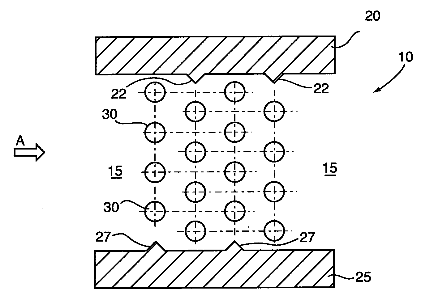
[0074]Prior to describing the preferred embodiments of the present invention, we will describe a prior art fluid treatment system such as the one taught in Blatchley described above.

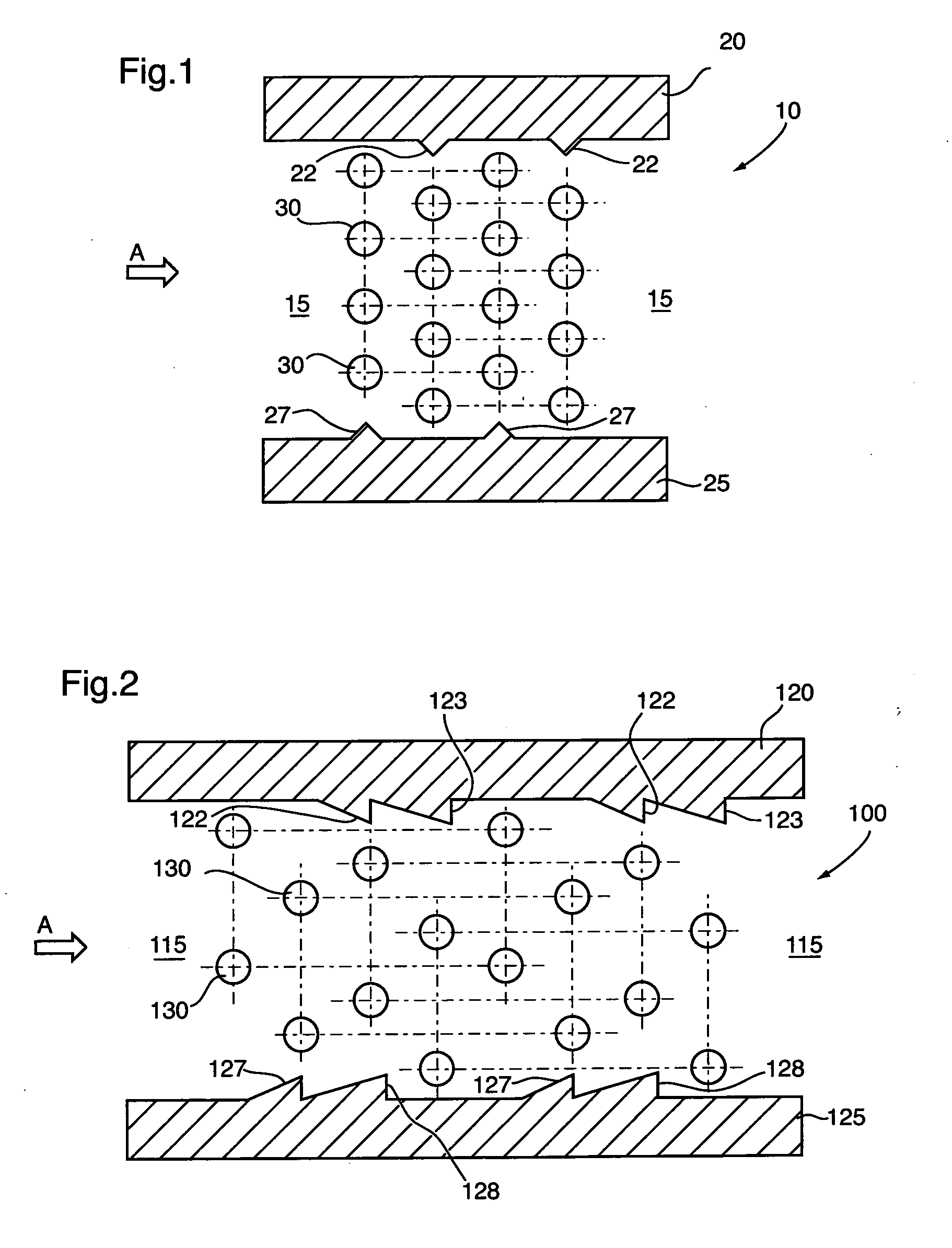
[0075]With reference to FIG. 1, there is illustrated a fluid treatment system 10 comprising a channel 15. Channel 15 comprises a pair of sidewalls 20,25. Open channel 15 is configured to receive a fluid flowing in the direction of arrow A.

[0076]Sidewall 20 comprises a pair of fluid diverters 22. Sidewall 25 comprises a pair of fluid diverters 27. Disposed in open channel 15 is a plurality of vertical oriented radiation source assemblies 30.

[0077]As can be seen from FIG. 1, fluid diverters 22,27 have the same profile (i.e., triangular) and project into channel 15 to the same degree.

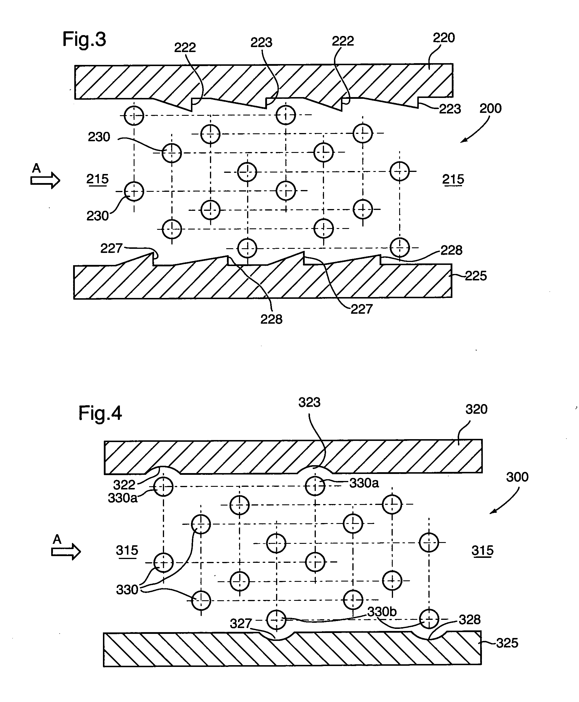
[0078]With reference to FIG. 2, there is illustrated a first preferred embodiment of a fluid treatment system 100 in accordance with the present invention. Fluid treatment system 100 comprises an open channel 115 and a pair of ...


PUM

PropertyMeasurementUnit
Pressureaaaaaaaaaa
Angleaaaaaaaaaa
Flow rateaaaaaaaaaa

Abstract

In one of its aspects, the present invention relates to a fluid treatment system comprising: an inlet; an outlet; a fluid treatment zone disposed between the inlet and the outlet. The fluid treatment zone: (i) comprises a first wall surface and a second wall surface opposed to the first wall surface, and (ii) having disposed therein at least one array of rows of radiation source assemblies. Each radiation source assembly has a longitudinal axis transverse to a direction of fluid flow through the fluid treatment zone and each of the first wall surface and the second wall surface comprises a first fluid deflector element and a second fluid deflector element. The first fluid deflector element projecting into the fluid treatment zone to a greater extent than the second fluid deflector element.

Description

FIELD OF THE INVENTION[0001]In one of its aspects, the present invention relates to a fluid treatment system, more particularly, an ultraviolet radiation water treatment system. In another of its aspects, the present invention relates to a method for treating a fluid, more particularly a method for irradiating water.DESCRIPTION OF THE PRIOR ART[0002]Fluid treatment systems are generally known in the art. More particularly, ultraviolet (UV) radiation fluid treatment systems are generally known in the art. Early treatment systems comprised a fully enclosed chamber design containing one or more radiation (preferably UV) lamps. Certain problems existed with these earlier designs. These problems were manifested particularly when applied to large open flow treatment systems which are typical of larger scale municipal waste water or potable water treatment plants. Thus, these types of reactors had associated with them the following problems:[0003]relatively high capital cost of reactor;[00...

Claims


Application Information

Patent Timeline
IPC IPC(8): C02F1/32
CPCC02F1/325C02F2201/328C02F2201/3227C02F2201/3225
Inventor MA, LI ZHENGTRAUBENBERG, GEORGEPENHALE, DOUGLAS
Owner TROJAN TECH
Learn More