Convective heater

a heating device and convection technology, applied in the direction of heater elements, light and heating apparatus, laminated elements, etc., can solve the problems of uncomfortable occupants of vehicle seats, chairs or other seat assemblies situated in cold environments

Active Publication Date: 2010-08-05
GENTHERM INC
View PDF101 Cites 67 Cited by
  • Summary
  • Abstract
  • Description
  • Claims
  • Application Information

AI Technical Summary

Benefits of technology

[0018]According to some embodiments, the heater and the first heat transfer assembly of the heater device are attached using adhesives, thermal grease, clips, bolts, other mechanical fasteners and / or any other connection device or method. In some embodiments, a Temperature Coefficient of Resistance (TCR) of at least one electrical conducting member is between about 1,500 and 3,500 ppm / ° C. (e.g., about 1,500, 1,600, 1,700, 1,800, 1,900, 2,000, 2,100, 2,2000, 2,300, 2,400, 2,500, 2,600, 2,700, 2,800, 2,900, 3,000, 3,100, 3,200, 3,300, 3,400, 3,500 ppm / ° C., ranges between such values, etc.). In other embodiments, the TCR of at least one conducting member is less than 1,500 ppm / ° C. (e.g., between about 0 and 1,500 ppm / ° C.) or greater than 3,500 ppm / ° C. (3,550, 3,600, 3,700, 3,800, 3,900, 4,000, 4,500, 5,000, 5,500, 6,000 ppm / ° C., values greater than 6,000 ppm / ° C., ranges between such values, etc.).
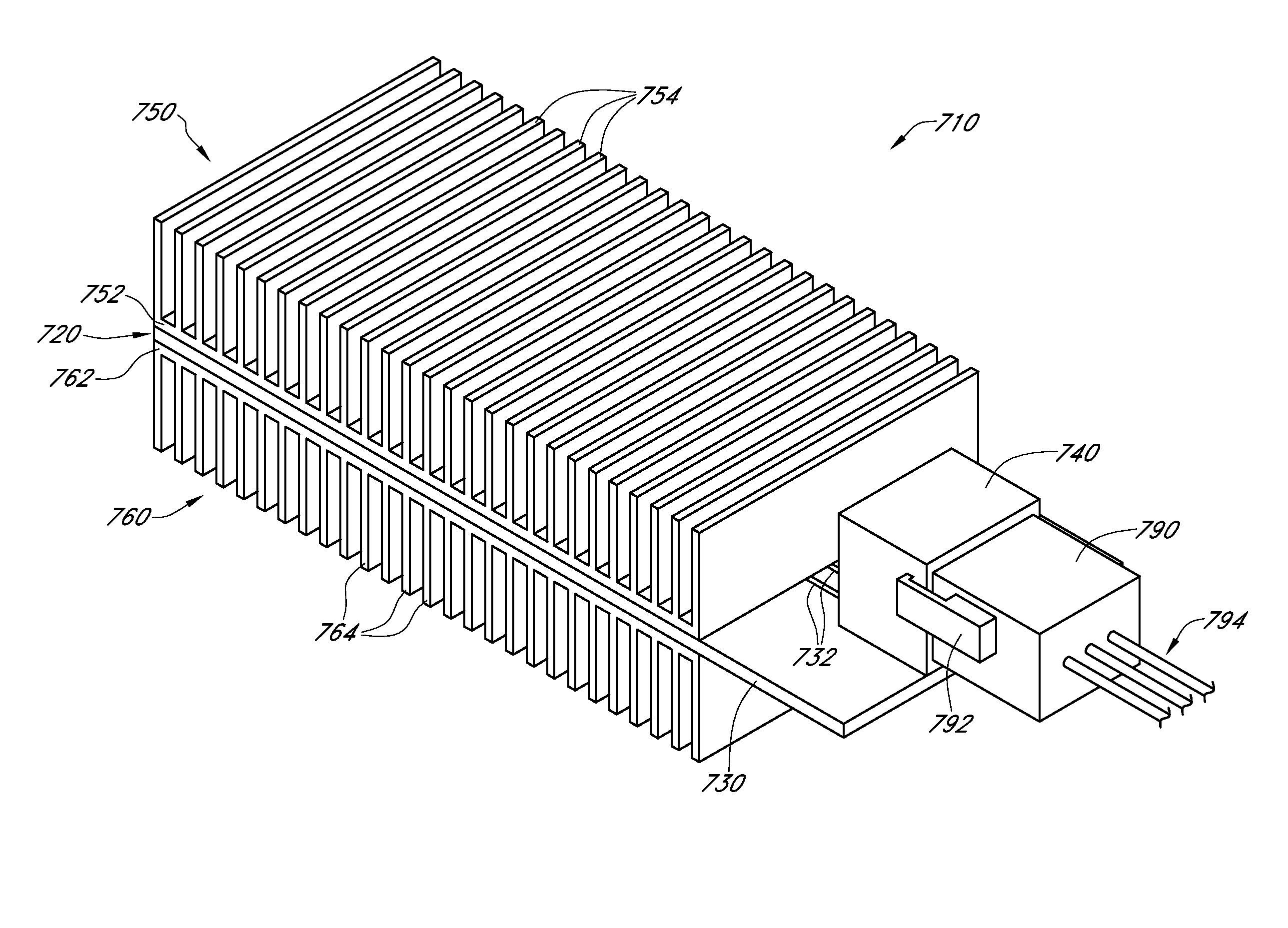
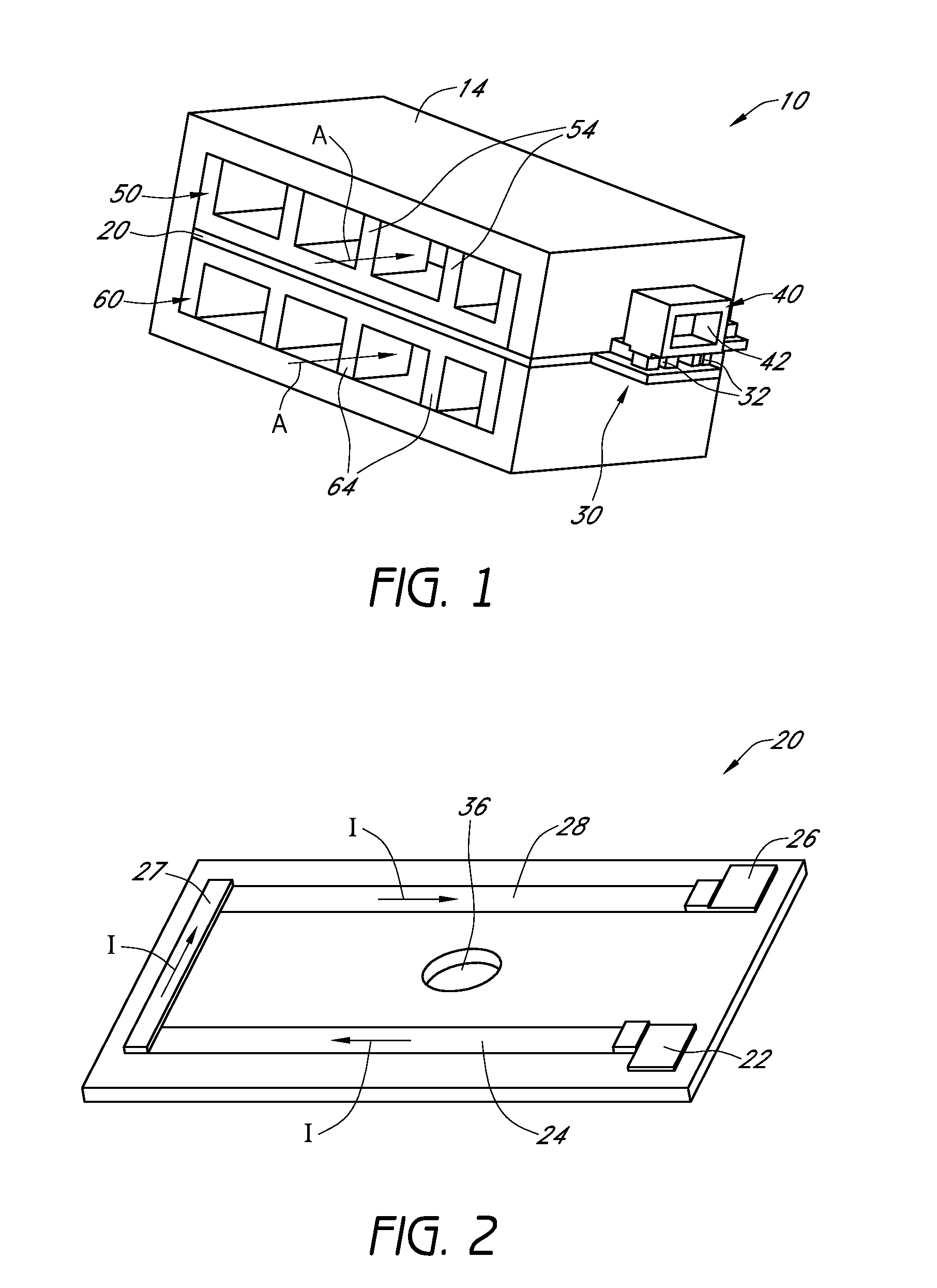
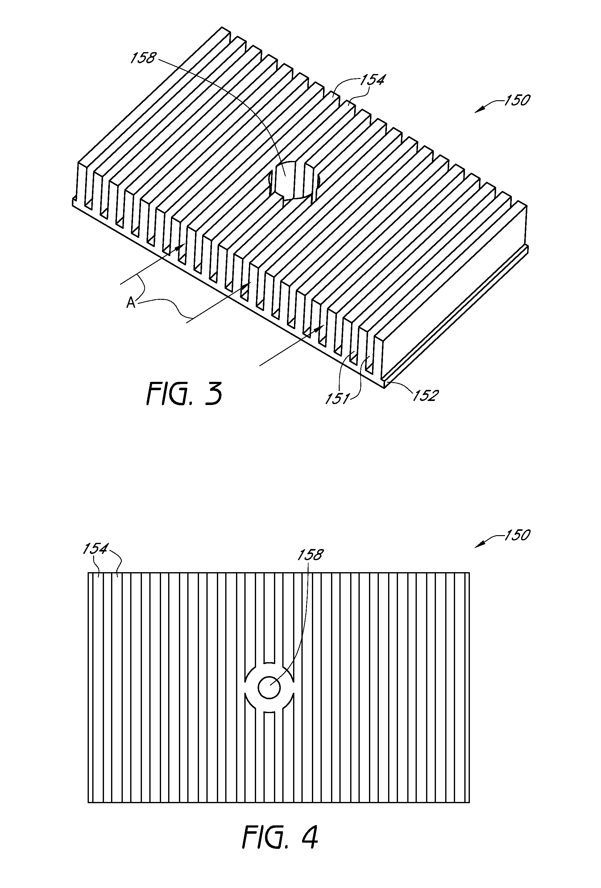
[0019]According to some embodiments, a climate control system for a seating assembly includes a heating device for thermally conditioning a fluid. In some arrangements, the heating device of the climate control system comprises a heat transfer assembly having a base which includes a first side and a second side, wherein the second side is generally opposite of the first side and wherein the first side comprises a plurality of heat transfer members through or near which fluid is configured to selectively pass. The heating device additionally includes a heater comprising at least one electrically conductive member which is configured to receive electrical current and convert it electrical current to heat. In some embodiments, at least a portion of the heat generated by the heater is transferred to the heat transfer members of the heat transfer assembly. In one embodiment, fluids passing through or near the heat transfer members are selectively heated when electrical current is provided to the heater. According to certain arrangements, the climate control system further comprises a fluid transfer device (e.g., fan, blower, etc.) configured to move fluid through the heating device and an outlet conduit located downstream of the heating device and the fluid transfer device, such that the outlet conduit is configured to deliver thermally conditioned fluid to a seating assembly.
[0020]According to some embodiments, the heater of the climate control system is positioned along the second side of the base of the heat transfer assembly such that the heat transfer assembly and the heater comprise a generally unitary structure. In another embodiment, at least one electrically conductive member comprises a conductive material formed directly on the base of the first heat transfer assembly. In other embodiments, at least one conductive material is deposited on the base using spraying, coating, printing, plating and / or any other device or method. In some embodiments, the climate control system is configured for use in an automobile seat or other vehicle seat. In other embodiments, the climate control system is configured for use in a bed (e.g., standard bed, hospital or other medical bed, etc.) and / or any other type of seating assembly (e.g., wheelchair, theater seat, office chair, sofa, etc.). In other embodiment, the heating device and / or other components of the climate control system are adapted to be used to thermally condition other types of devices or specific areas or regions. In some embodiments, the heating device is positioned within a housing of the fluid transfer device. In other arrangements, the heating device is positioned upstream or downstream of the fluid transfer device (e.g., fan, blower, etc.). In another embodiment, the climate control system additionally includes one or more thermoelectric devices (e.g., Peltier circuit, another type of heat pump, etc.) and / or other types of heating and / or cooling devices to selectively cool fluids being delivered to the outlet conduit. In one embodiment, a Temperature Coefficient of Resistance (TCR) of the at least one electrically conductive member is between about 1,500 and 5,000 ppm / ° C.

Problems solved by technology

For example, a vehicle seat, chair or other seat assembly situated in a cold environment can be uncomfortable to the occupant.

Method used


Image

  • Convective heater
  • Convective heater
  • Convective heater

Examples


Embodiment Construction

[0064]The discussion below and the figures referenced herein describe various embodiments of heating devices, devices and systems configured to include such a heating devices and methods utilizing such devices or systems. A number of embodiments of such devices, systems and methods are particularly well suited to provide heated air or other fluids to one or more portions of vehicle seats (e.g., seat back portion, seat bottom portion, neck portion, headrest region, other portions of an automotive seat or other vehicle seat, etc.). However, the heating devices, systems and other components (e.g., blowers, fans, other fluid transfer devices, housings, thermoelectric devices, etc.) making use of such heating devices and other thermally conditioning features disclosed herein may be incorporated into other types of seat assemblies, including, without limitation, beds (e.g., hospital beds, other medical beds, beds for home use, hotel beds, etc.), recliner chairs, sofas, office chairs, airp...


PUM


Abstract

A heating device comprises a heater having a first surface and a second surface, with the second surface being generally opposite of the first surface. The heater is configured to receive an electrical current and convert it to heat. The heating device additionally includes at least one heat transfer assembly positioned along the first and/or second surface of the heater. In one embodiment, the heat transfer assembly includes a plurality of fins that generally define a plurality of fin spaces through which fluids may pass. In some arrangements, the heating device comprises an outer housing that at least partially surrounds the heater and one or more of the heat transfer assemblies. Heat generated by the heater is transferred to the fins of the heat transfer assembly. In addition, fluids passing through the fin spaces are selectively heated when electrical current is provided to the heater.

Description

CROSS REFERENCE TO RELATED APPLICATIONS[0001]This application claims the priority benefit under 35 U.S.C. §119(e) of U.S. Provisional Patent Application No. 61 / 148,019, filed Jan. 28, 2009, the entirety of which is hereby incorporated by reference herein.BACKGROUND[0002]1. Field of the Inventions[0003]This application generally relates to heating devices and systems, and more specifically, to convective heating devices and systems configured for use in climate controlled (e.g., heated, ventilated, etc.) seating assemblies.[0004]2. Description of the Related Art[0005]Temperature modified air for environmental control of an automobile, other vehicles or any other living or working space is typically provided to relatively extensive areas, such as an entire automobile interior, selected offices or suites of rooms within a building (e.g., houses, hospitals, office buildings, etc.) and the like. In the case of enclosed areas, such as automobiles, trains, airplanes, other vehicles, homes,...

Claims


Application Information

Patent Timeline
Patent Type & Authority Applications(United States)
IPC IPC(8): H05B1/00H05B3/02
CPCF24H3/002F24H3/0405F24H9/2071F24H3/0482F28F3/02F28F3/025F28D1/024
Inventor WALSH, RYAN
Owner GENTHERM INC
Why Eureka
Try Eureka