Mapping service components in a broadcast environment

a technology of broadcast environment and service components, applied in the field of mapping service components in a broadcast environment, can solve the problems of increasing the resources necessary to broadcast multiple services at once, components cannot be shared between different services,

Active Publication Date: 2010-08-05
SAMSUNG ELECTRONICS CO LTD
View PDF14 Cites 94 Cited by
  • Summary
  • Abstract
  • Description
  • Claims
  • Application Information

AI Technical Summary

Benefits of technology

[0003]One or more aspects relate to a signaling structure for broadcast transmissions in which services or service components thereof are mapped to multiple physical layer transmission channels (PLP) through logical layer pipes. Logical layer pipes (LLP) are associated with either the service or service components or both as well as a set of one or more PLPs to which the service components are mapped. By using LLPs, different services may share service components by associating each LLP, corresponding to each of the different services, with the PLP corresponding to the service component to be shared. Additionally, the use of an LLP allows for different service components of a service to be mapped to different PLPs. Accordingly, for example different error correction or error detection protocols may be applied to the different service components if needed.

Problems solved by technology

Accordingly, components cannot be shared between different services, increasing the resources necessary to broadcast multiple services at once.

Method used


Image

  • Mapping service components in a broadcast environment
  • Mapping service components in a broadcast environment
  • Mapping service components in a broadcast environment

Examples


Embodiment Construction

[0025]In the following description of the various embodiments, reference is made to the accompanying drawings, which form a part hereof, and in which are shown by way of illustration various embodiments in which the invention may be practiced. It is to be understood that other embodiments may be utilized and structural and functional modifications may be made without departing from the scope of the present invention.

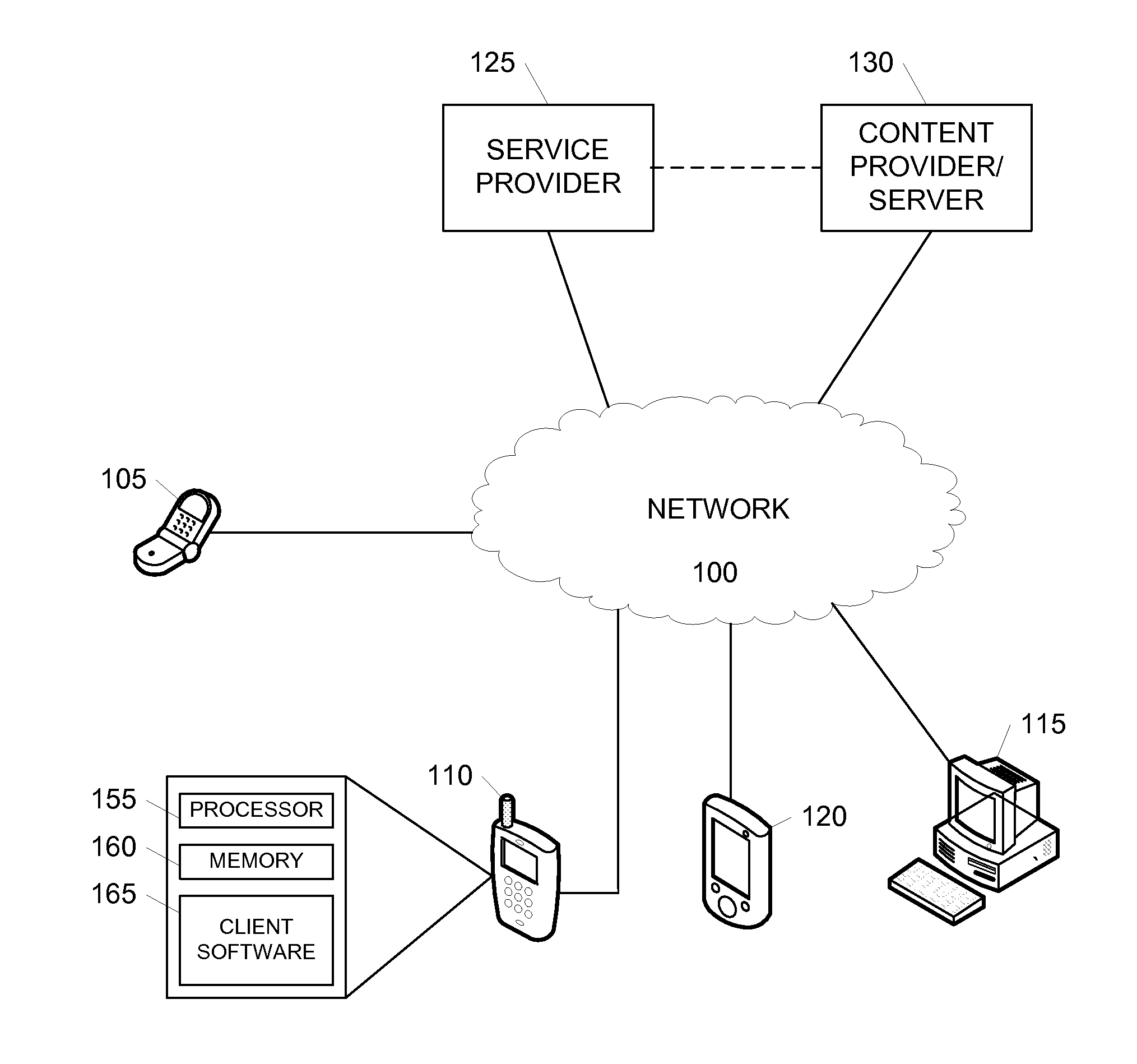
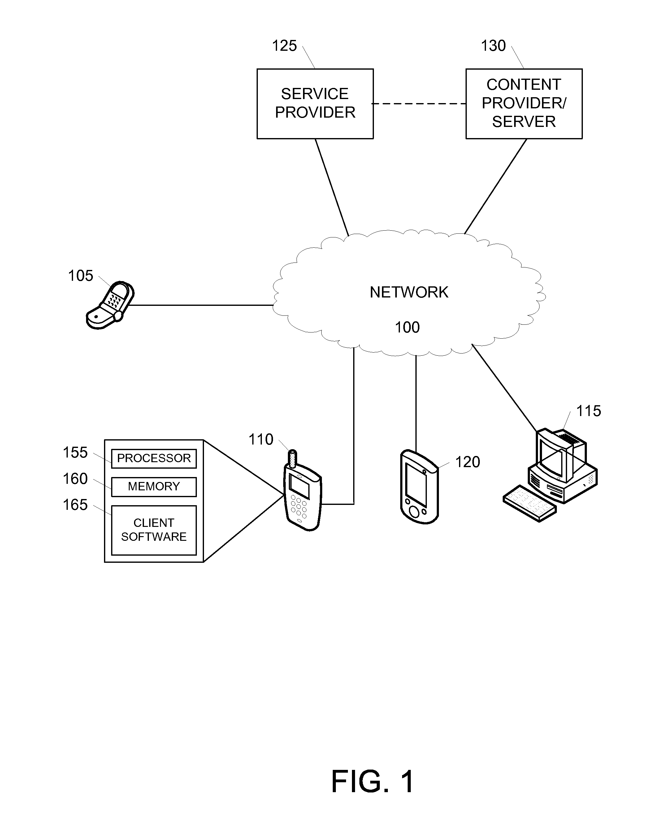
[0026]FIG. 1 illustrates an example communication network through which various inventive principles may be practiced. A number of computers and devices including mobile communication device 105, mobile phone 110, personal digital assistant (PDA) or mobile computer 120, personal computer (PC) 115, service provider 125 and content provider 130 may communicate with one another and with other devices through network 100. Network 100 may include wired and wireless connections and network elements, and connections over the network may include permanent or temporary connection...


PUM


Abstract

Services and service components in a broadcast network may be mapped to disparate physical layer transmission channels (PLPs) using logical layer pipes (LLPs). The use of LLPs allows different service components of a single service to be mapped to physical layer transmission channels (PLPs). Accordingly, service components may be shared among different services. Additionally or alternatively, different functions (e.g., different error detection or correction protocols) may be applied to each service components of a service. A receiver may identify services, service components and corresponding PLPs based on LLP identifiers. The receiver may then access and receive desired services and service components through the identified PLPs.

Description

BACKGROUND[0001]Content and other services broadcast in a network may often include many service components. For example, a high definition video may include a standard definition component that provides a base amount of content data and a high definition component that supplements the base content data with high definition information. In current broadcast protocols, such service components are mapped to and carried in a physical layer—according to e.g. the OSI model—through pipes. A physical layer pipe provides a transmission channel through which a sender may transmit data as raw bits to one or more receiving devices. However, current protocols require that all service components of a given service be mapped to the same pipe. Accordingly, components cannot be shared between different services, increasing the resources necessary to broadcast multiple services at once. Additionally, requiring that service components be mapped to the same pipe can inhibit different functions such as...

Claims


Application Information

Patent Timeline
Patent Type & Authority Applications(United States)
IPC IPC(8): H04W4/00
CPCH04W36/385
Inventor VARE, JANIALAMAUNU, JYRKIPEKONEN, HARRI J.VESMA, JUSSI
Owner SAMSUNG ELECTRONICS CO LTD
Why Eureka
Try Eureka