

Signal bandwidth extending apparatus
a technology of signal bandwidth and extending apparatus, applied in the field of signal bandwidth extending apparatus, can solve problems such as heavy computational load
- Summary
- Abstract
- Description
- Claims
- Application Information
AI Technical Summary
Benefits of technology
Problems solved by technology
Method used
Image

Examples
first embodiment
Modified Example of First Embodiment
[0114]A non-target signal suppressing unit 34 as shown in FIG. 8 may be added to the signal bandwidth extending unit 3. The non-target signal suppressing unit 34 is provided with a non-target signal section determining unit 341, a non-target signal level estimating unit 342, and a non-target signal suppression processor 343. As shown in FIG. 9, the non-target signal suppression processor 343 is provided with a frequency domain transforming unit 343A, a power calculating unit 343B, a power calculating unit 343C, a suppression gain calculating unit 343D, a spectrum suppressing unit 343E, and a time domain transforming unit 343F.
[0115]The non-target signal suppressing unit 34 suppresses the non-target signal components in the input signal x[n] using the target signal degree type[f] output from the target signal degree calculating unit 31, and inputs the signal x_ns[n], in which the non-target signal components are suppressed to the signal bandwidth e...
second embodiment
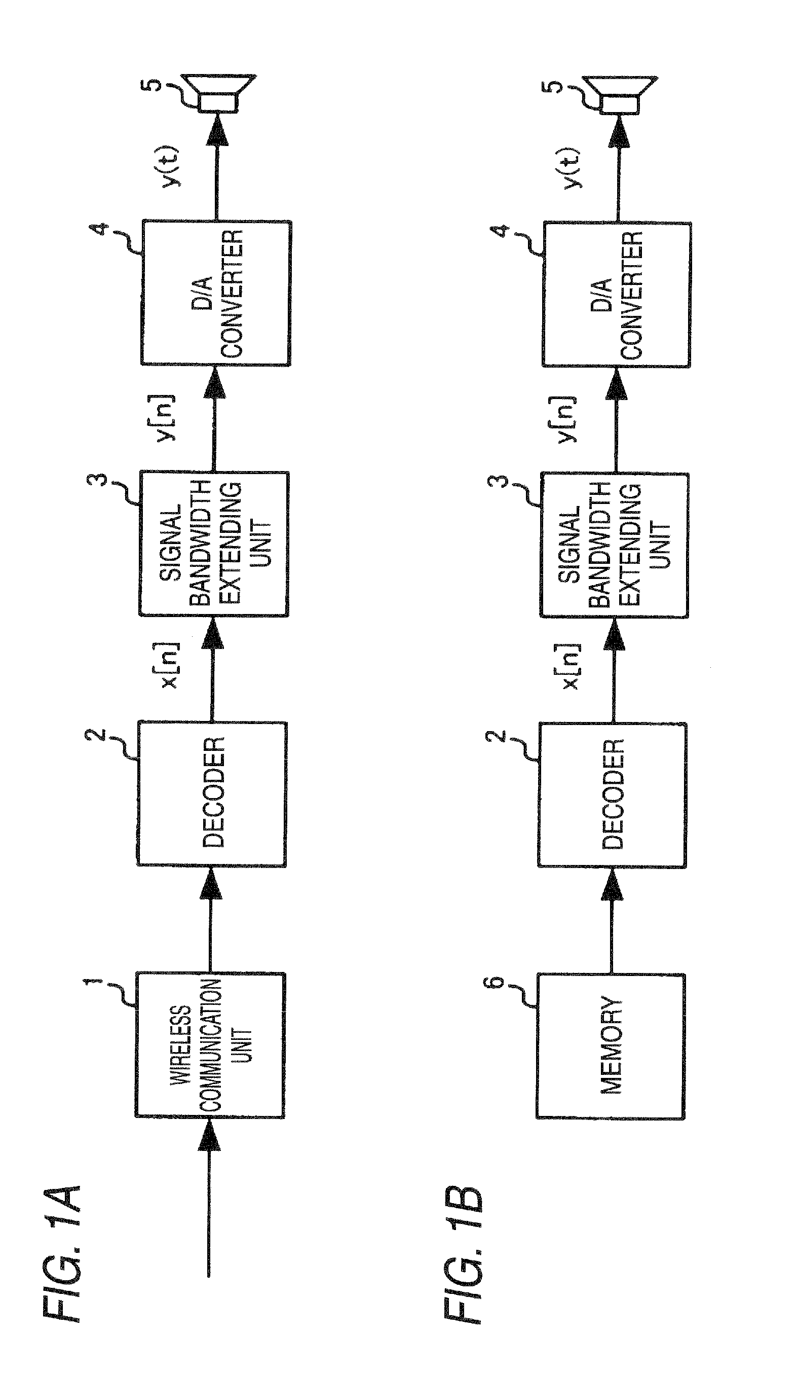
[0127]Next, a second embodiment of the invention will be described now. Since the configuration of this embodiment is the same as that of the first embodiment described with reference to FIGS. 1A and 1B, the description thereof will be omitted. FIG. 10 shows the configuration of the signal bandwidth extending unit 3 according to this embodiment. Further, in the following description the same configurations as those of the first embodiment are designated by the same reference numerals. For convenience of explanation, the description already given will be omitted as needed.
[0128]In the second embodiment, the input signal x[n] (n=0, 1, . . . , N−1) of the signal bandwidth extending unit 3 is limited in the bandwidth from fs_nb_low [Hz] to fs_nb_high [Hz]. The sampling frequency is changed from the sampling frequency fs [Hz] to the higher sampling frequency of fs′ [Hz] by the bandwidth extending process of the signal bandwidth extending unit 3. The input signal is extended to the bandwi...
third embodiment
[0157]Next, a third embodiment of the invention will be described now. Since the configuration of this embodiment is the same as that of the first embodiment described with reference to FIGS. 1A and 1B, the description thereof will be omitted. FIG. 18 shows the configuration of the signal bandwidth extending unit 3 according to this embodiment. Further, in the following description, the same configurations as those of the above-mentioned embodiment are designated by the same reference numerals. For convenience of explanation, the description already given will be omitted as needed.
[0158]In the third embodiment, the signal bandwidth extending unit 3 is configured to use a target signal degree calculating unit 38 instead of the target signal degree calculating unit 31 of the signal bandwidth extending unit 3 according to the first embodiment, and a signal bandwidth extension processor 39 instead of the signal bandwidth extension processor 33 according to the first embodiment. In addit...
PUM
 Abstract
Description
Claims
Application Information