Display control apparatus and display control method

Inactive Publication Date: 2010-08-05
CANON KK
View PDF12 Cites 38 Cited by
  • Summary
  • Abstract
  • Description
  • Claims
  • Application Information

AI Technical Summary

Benefits of technology

[0012]The present invention has been made in consideration of the above situation, and provided is a display control apparatus and display control method, which can appropriately execute display control upon repetition of the zoom-in and zoom-out processes of a partial image to be displayed in a display range.

Problems solved by technology

For this reason, when the zoom-in and zoom-out processes of an image to be displayed within the display range are repeated, the display range is gradually moved to the center of the image, thus posing a problem.

Method used


Image

  • Display control apparatus and display control method
  • Display control apparatus and display control method
  • Display control apparatus and display control method

Examples


first embodiment

[0036]The first embodiment of the present invention will be described hereinafter. In the present invention, when a part of an image is displayed on a display area having a fixed display size, a display range which indicates a region of the image to be displayed on the display area is increased or decreased with reference to a point farthest from the center of the image in the display range.

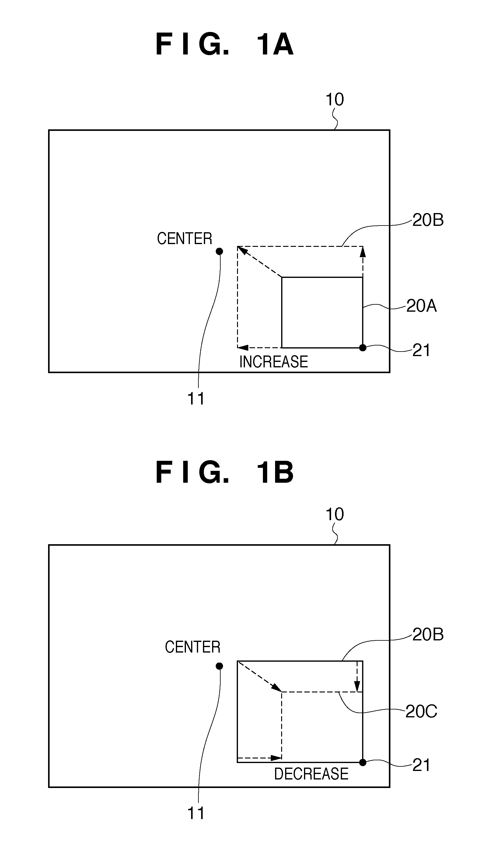
[0037]An overview of the present invention will be described below with reference to FIGS. 1A and 1B. Referring to FIGS. 1A and 1B, assume that a part included in a display range 20A (or a display range 20B or 20C) of an image 10 is displayed on a display area having a fixed display size while its size is increased or decreased to fit the display size. Therefore, when the display range 20A is increased, a zoom-in ratio of a partial image to be displayed on the display area becomes small. On the other hand, when the display range 20A is decreased, the zoom-in ratio of the partial image to be displ...

second embodiment

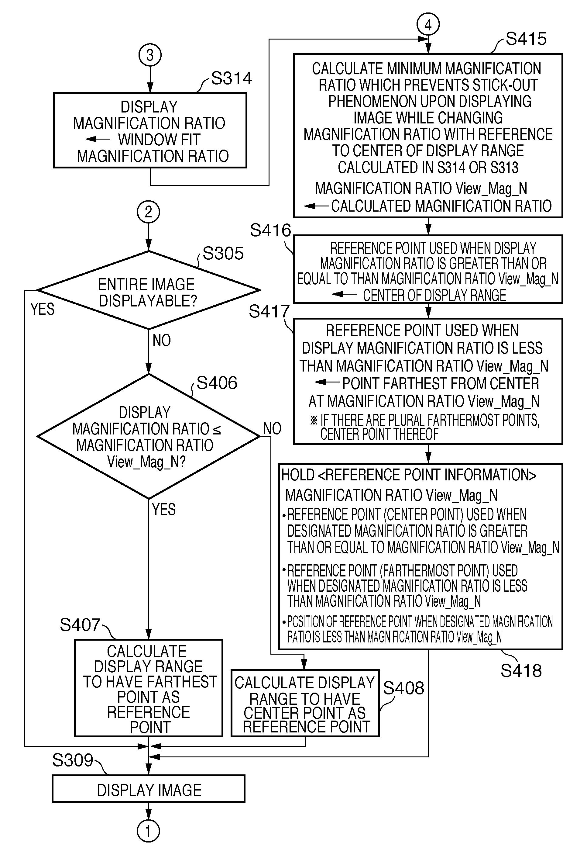
[0178]The second embodiment of the present invention will be described hereinafter. In the second embodiment, when a display range is located near the center of an entire image, the center of the display range is set as a reference point for zoom-in and zoom-out processes in addition to the processing of the aforementioned first embodiment.

[0179]More specifically, a display magnification ratio is calculated so as to prevent the display range, which is increased using the center of the display range as the reference point, from sticking out from the entire image. When a display magnification ratio designated by a user operation is greater than or equal to a display magnification ratio which can prevent the display range after the increase processing from sticking out from the entire image, the increase processing of the display range is executed using the center of the display range as a reference point. On the other hand, when the designated display magnification ratio is less than ...


PUM


Abstract

A display control apparatus controls to execute variable magnification processing of a partial image of an image indicated by a display range, and to display the partial image in a display area. The display control apparatus comprises a calculation unit which obtains a vertex / vertexes of the display range farthest from a center of the image, and sets the vertex or a center point of the vertexes as a reference point, a changing unit which changes a size of the display range while keeping the position of the reference point, a moving unit which moves the display range in the image, and a display control unit which controls to execute the variable magnification processing of the partial image, and to display the partial image in the display area. The calculation unit re-calculates the reference point in response to movement of the display range in the image by the moving unit.

Description

BACKGROUND OF THE INVENTION[0001]1. Field of the Invention[0002]The present invention relates to a display control apparatus and display control method, which display an image on a display area at a variable magnification ratio.[0003]2. Description of the Related Art[0004]In recent years, the performance of image sensing devices such as CCDs and CMOS sensors has been enhanced, and the number of pixels which can be used by them to sense an image has increased compared to conventional devices. A digital camera, which includes an image sensing device having a large number of pixels, can record image data having an image size, which cannot be entirely displayed on a display having a standard number of display pixels.[0005]It has also become easy for end users to confirm whether or not a sensed image is visually in focus or whether or not an image adjustment result such as contrast adjustment or edge emphasis is desired by zooming out or in the sensed image to be displayed. For example, ...

Claims


Application Information

Patent Timeline
Patent Type & Authority Applications(United States)
IPC IPC(8): G06F3/048G09G5/00
CPCG06F3/0481G06F2203/04806G09G5/14G09G2340/045G09G2340/0464G09G2354/00G06T11/60
Inventor MIKAWA, CHIAKI
Owner CANON KK
Why Eureka
Try Eureka